
Built-in vehicle stopping device and using method thereof

A blocking device, built-in technology, applied in the field of built-in vehicle blocking devices, can solve the problems of large area, easy to be found, time-consuming and labor-intensive use process, etc., to save manpower and material resources, convenient transportation, high concealment Effect

Active Publication Date: 2022-03-04
SICHUAN JIUZHOU ELECTRIC GROUP
View PDF22 Cites 0 Cited by
  • Summary
  • Abstract
  • Description
  • Claims
  • Application Information

AI Technical Summary

Problems solved by technology

[0004] In view of the above analysis, the present invention aims to provide a built-in vehicle arresting device and its use method to solve the problems that the existing vehicle arresting device occupies a large area and is easy to be found when it is not in use, and the use process is time-consuming and laborious.

Method used


Image

  • Built-in vehicle stopping device and using method thereof
  • Built-in vehicle stopping device and using method thereof
  • Built-in vehicle stopping device and using method thereof

Examples


Embodiment 1

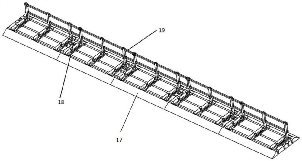
[0040] A specific embodiment of the present invention discloses a built-in vehicle blocking device, which is a detachable structure, such as figure 1 As shown, it includes a plurality of blocking units, and the two sides of the blocking units are symmetrically provided with the slots 18 of the deceleration base connectors, and the blocking units are matched with the slots 18 of the deceleration base connectors through the base connectors. connected so that multiple blocking units are connected side by side to form a complete built-in vehicle blocking device. The whole device occupies a small space; at the same time, it is convenient and fast to transport, saves manpower and material resources, and can be quickly deployed.

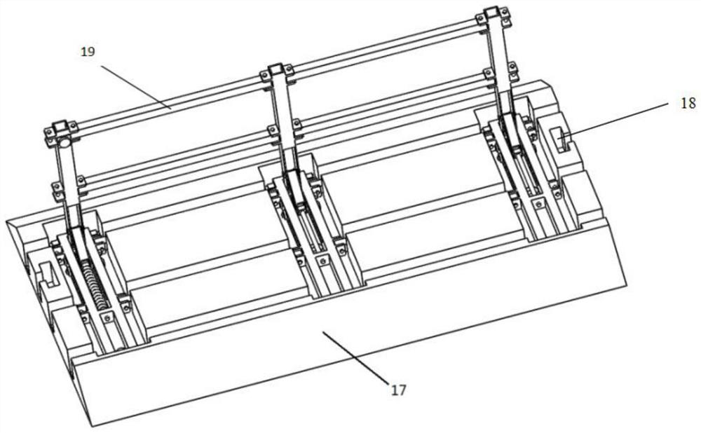
[0041] Further, as Figure 2-Figure 3 As shown, the blocking unit includes a deceleration base 17 and an intercepting support frame. The upper surface of the deceleration base 17 is provided with transverse grooves and longitudinal grooves, and the transve...

Embodiment 2

[0065] A method for using a built-in vehicle blocking device, using the built-in vehicle blocking device in Embodiment 1, specifically comprising the following steps:

[0066] S1: The electric chuck 8 and the electric chuck block 14 lose their magnetic attraction:

[0067] When the device is in a non-working state, the intercepting support frame is in a folded state in the transverse groove and the longitudinal groove, and the vertical blocking rod 13 and the lying blocking rod 5 are stacked up and down to overlap each other.

[0068] At this time, the electric chuck 8 and the electric chuck block 14 are in a power-off state, and the two are attracted together by magnetic force, and vehicles can pass on the device.

[0069] When there is a need to intercept the vehicle, the staff controls the magnetic state of the electric chuck 8 and the electric chuck block 14 by starting the remote control, so that the two are instantly energized and lose the magnetic attraction force. The...


PUM


Abstract

The invention relates to a built-in vehicle stopping device and a using method thereof, belongs to the field of motor vehicle stopping, and solves the problem that a vehicle stopping device in the prior art is large in occupied area and easy to find. A built-in type vehicle stopping device comprises a plurality of stopping units, and the stopping units are connected in a clamped mode through base connecting pieces and speed reduction base connecting piece inserting grooves. The stopping unit comprises a speed reduction base and a stopping supporting frame which are connected in a matched mode; the intercepting supporting frame is of a foldable structure and comprises a plurality of folding pieces and a plurality of connecting rods, and the folding pieces are arranged in parallel and are connected and combined with the connecting rods through steel ball bolts; the upper surface of the speed reduction base is provided with a plurality of grooves which are transversely and longitudinally staggered in a perpendicular mode, and when the intercepting supporting frame is in a folded state, the intercepting supporting frame can be contained in the grooves. The vehicle stopping device has the advantages of being small in occupied area, not prone to being perceived, fast to operate and convenient to use.

Description

technical field [0001] The invention relates to the technical field of motor vehicle blocking, in particular to a built-in vehicle blocking device and a usage method thereof. Background technique [0002] The past ten years is a period of rapid development of my country's automobile industry. At present, there are a large number of motor vehicles. Sometimes it is necessary to temporarily block and check the intersection due to work needs. At this time, it is necessary to quickly and temporarily intercept motor vehicles, so a vehicle blocking device is required. . [0003] Most of the vehicle blocking devices in the prior art are directly exposed on the road surface, and they are large in size and can be found by the driver at a glance. Once they are found, they lose their blocking meaning, and the driver will inevitably try to avoid them. Temporary vehicle interception is best done by surprise, so as not to cause an uncontrollable situation. At the same time, the existing c...

Claims


Application Information

Patent Timeline
IPC IPC(8): E01F13/04E01F13/08
CPCE01F13/044E01F13/08
Inventor 白竹川吴磊朱鹏龙
Owner SICHUAN JIUZHOU ELECTRIC GROUP
Learn More