Supercharge Your Innovation With Domain-Expert AI Agents!

5GassiveMIMO electrically tunable antenna structure

An electronically adjustable antenna and antenna technology, which is applied to the connection of antenna grounding switch structures, antennas, and antenna arrays, etc., can solve the problems of high integration requirements, high cost, and increasing number of antenna products, and achieve low coupling loss and high orientation. the effect of reducing the size of the sheet

Pending Publication Date: 2022-03-04
江苏富宇鸿通信科技有限公司
View PDF0 Cites 0 Cited by
  • Summary
  • Abstract
  • Description
  • Claims
  • Application Information

AI Technical Summary

Problems solved by technology

[0002] 5G Massive MIMO electronically tunable antennas need to integrate phase shifter modules, RET modules, and calibration network modules on the basis of conventional Massive MIMO antennas. The integration requirements are high, which poses a huge challenge to the realization of reliability and electrical performance.
[0003] The existing 5G Massive MIMO electronically adjustable antenna solution has a complex structure and low integration, which leads to high product size, weight, and high cost. On the other hand, there are multiple 5G commercial frequency bands in different regions of the world. In general, there are two solutions to the existing solutions for the 5G frequency band in the region. One is to make the internal components of the antenna more complicated to achieve broadband characteristics. In this way, the manufacturing process of the antenna will become more complicated and the cost will not be obtained Effective control, the second is to develop different antennas for different frequency bands, so that the number of antenna products will increase, so that the R&D and design costs and operation and maintenance costs of antenna manufacturers will increase relatively

Method used


Image

  • 5GassiveMIMO electrically tunable antenna structure
  • 5GassiveMIMO electrically tunable antenna structure
  • 5GassiveMIMO electrically tunable antenna structure

Examples


Embodiment Construction

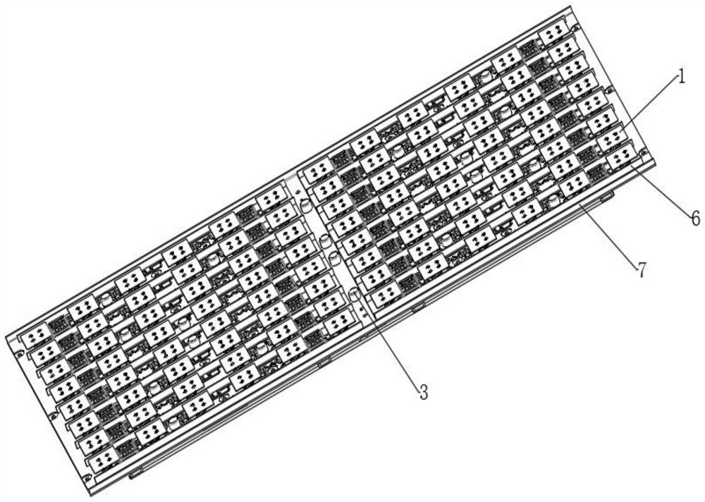
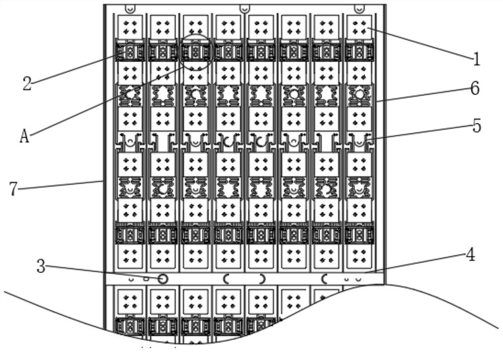
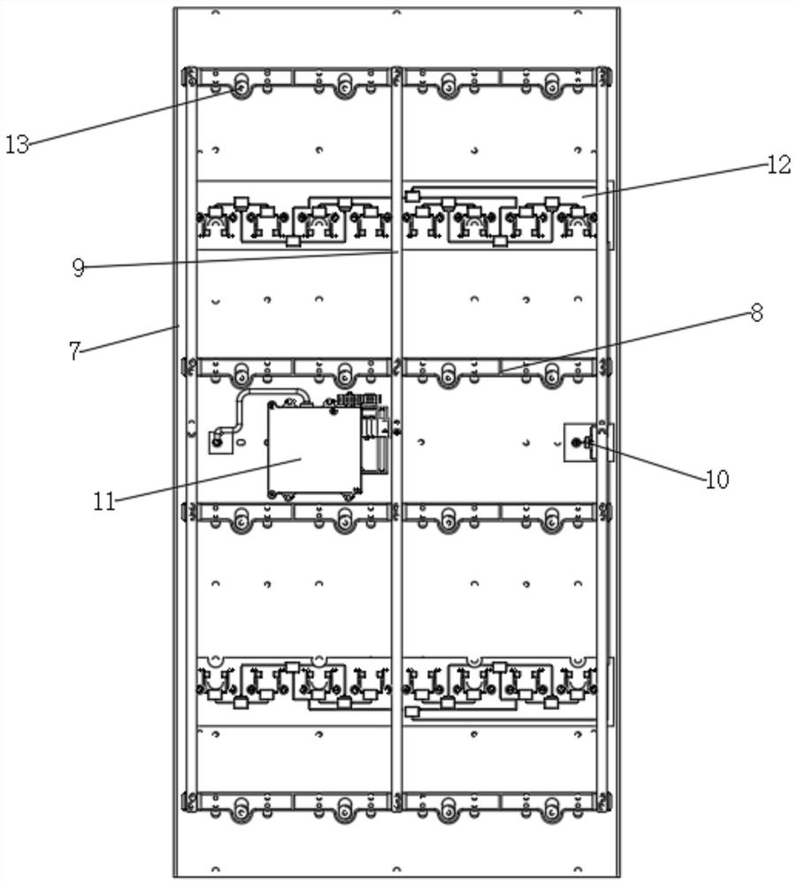
[0030] The embodiment of the present invention discloses a 5GMassiveMIMO electrically adjustable antenna structure, such as Figure 1-10 shown, including:

[0031] The antenna power distribution network board 6, the front of the antenna power distribution network board 6 is fixedly connected with a plurality of radiation units 1, the front of the antenna power distribution network board 6 is fixedly connected with a plurality of phase shifter modules 2, the antenna power distribution network board 6 The front is fixedly connected with a plurality of feed cores 5, and the other ends of the multiple feed cores 5 are respectively electrically connected with the calibration network board. The front of the antenna power distribution network board 6 is fixedly connected with a partition wall 4, and the partition wall 4 is made of PCB material. , can pass through the reflow soldering equipment together with the radiation unit 1, one-time furnace welding, the front of the antenna powe...


PUM


Abstract

The invention discloses a 5GassiveMIMO (multiple input multiple output) electrically tunable antenna structure, and relates to the technical field of communication base station antennas. Comprising an antenna power division network board, the front surface of the antenna power division network board is fixedly connected with a plurality of radiation units, a plurality of phase shifter modules and a plurality of feed cores, and the phase shifter modules and the feed cores are fixedly connected to the front surface of the antenna power division network board. The other ends of the plurality of feed cores are electrically connected with the calibration network board, the front surface of the antenna power division network board is fixedly connected with an isolation wall, the front surface of the antenna power division network board is provided with a plurality of antenna housing supporting columns, the back surface of the antenna power division network board is provided with a reflection board, and the reflection board is connected with the antenna housing supporting columns. According to a conventional antenna scheme, a phase shifter is designed on the back face of a reflecting plate of the antenna, and in the scheme, the phase shifter is integrated on an antenna power dividing plate, namely the front face of the reflecting plate, of an antenna radiation unit, so that the scheme has obvious advantages in product thickness.

Description

technical field [0001] The invention relates to the technical field of communication base station antennas, in particular to a 5GMassive MIMO electrically adjustable antenna structure. Background technique [0002] 5G Massive MIMO electronically tunable antennas need to integrate phase shifter modules, RET modules, and calibration network modules on the basis of conventional Massive MIMO antennas. The integration requirements are high, which poses a huge challenge to the realization of reliability and electrical performance. [0003] The existing 5G Massive MIMO electronically adjustable antenna solution has a complex structure and low integration, which leads to high product size, weight, and high cost. On the other hand, there are multiple 5G commercial frequency bands in different regions of the world. In general, there are two solutions to the existing solutions for the 5G frequency band in the region. One is to make the internal components of the antenna more complicate...

Claims


Application Information

Patent Timeline
Patent Type & Authority Applications(China)
IPC IPC(8): H01Q1/36H01Q1/50H01Q1/42H01Q1/12H01Q15/14H01Q21/00
CPCH01Q1/36H01Q1/50H01Q1/42H01Q1/12H01Q15/14H01Q21/00
Inventor 李传奇陈文高其金赵伟
Owner 江苏富宇鸿通信科技有限公司
Features
  • R&D
  • Intellectual Property
  • Life Sciences
  • Materials
  • Tech Scout
  • Unparalleled Data Quality
  • Higher Quality Content
  • 60% Fewer Hallucinations
Learn More