High-low voltage switch cabinet device based on intelligent heat dissipation and waterproof functions
A technology of high and low voltage switch and waterproof device, applied in the field of high and low voltage switchgear
- Summary
- Abstract
- Description
- Claims
- Application Information
AI Technical Summary
Problems solved by technology
Method used
Image
Examples
Embodiment 1
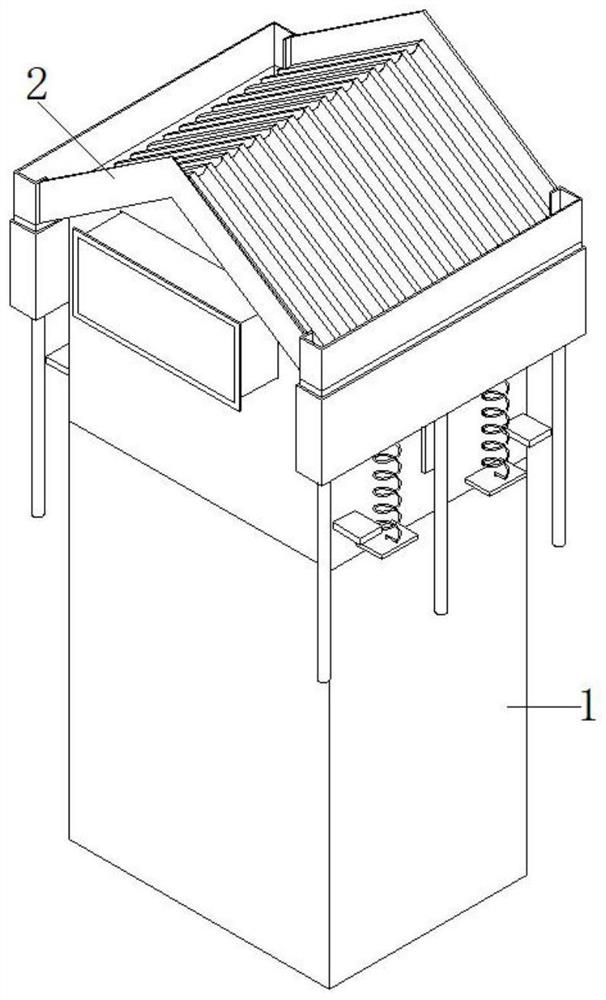
[0033] see figure 1 , figure 2 , Figure 4 As shown, the present invention is a high and low voltage switchgear device based on intelligent heat dissipation and waterproof functions, including a high and low voltage switchgear 1, and an intelligent heat dissipation and waterproof device 2 is arranged on the top of the high and low voltage switchgear 1.
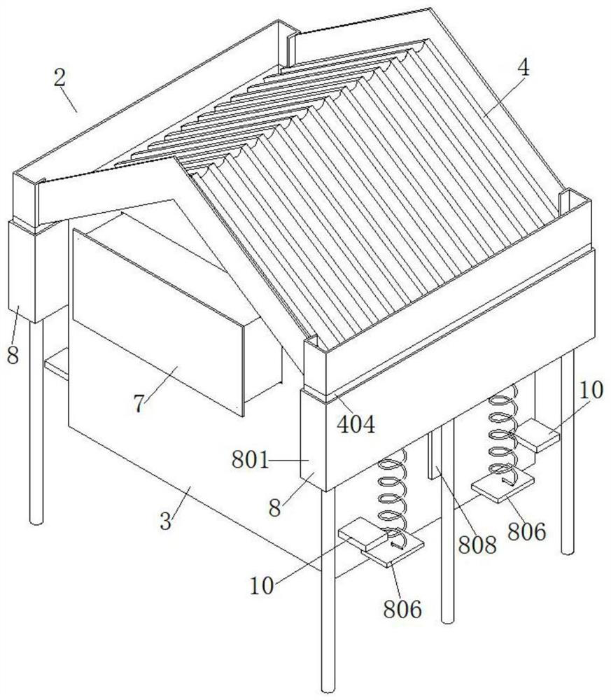
[0034] The intelligent heat dissipation and waterproof device 2 includes a device housing 3 , a waterproof mechanism 4 for a shelter, and a driving mechanism 8 . The top of the device housing 3 is provided with a rain shelter waterproof mechanism 4 . The bottom of the device housing 3 is fixedly connected to the top of the high and low voltage switch cabinet 1 , and the inner cavity of the device housing 3 communicates with the interior of the high and low voltage switch cabinet 1 . The rain shelter waterproof mechanism 4 includes a rain shield 401 , a shielding plate 403 , and a flow guide housing 404 . The surface of th...
Embodiment 2
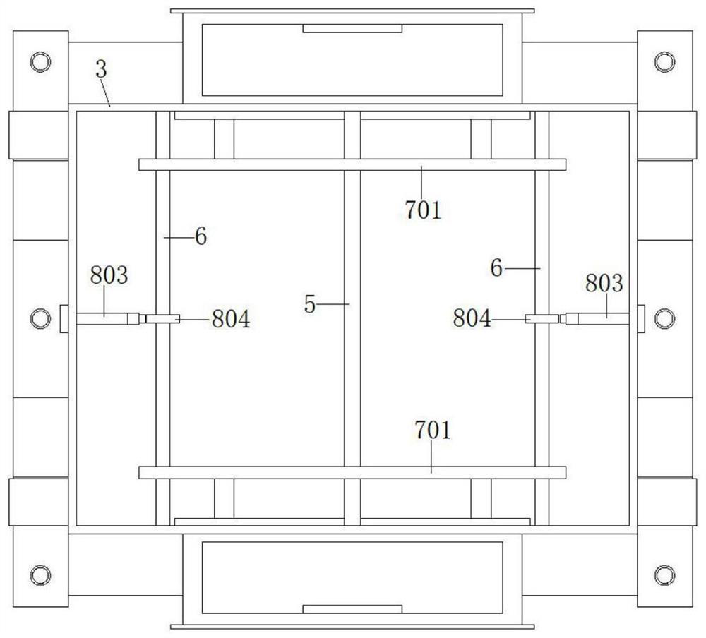
[0037] Based on the technical solution described in the first embodiment above. see Figure 2-8 As shown, the intelligent heat dissipation and waterproof device 2 also includes a transverse guide plate 5 , a transverse combination screw rod 6 , and a heat dissipation mechanism 7 . A transverse guide plate 5 is arranged between a group of relative inner surfaces of the inner chamber of the device housing 3, and two transverse combination screw rods 6 are rotationally connected between a group of relative inner surfaces of the inner cavity of the device housing 3, and the transverse guide plate 5 It is located between two transverse combination screw rods 6 . The horizontal combination screw rod 6 is formed by fixed connection of two screw rods with opposite thread directions end to end.
[0038] A heat dissipation mechanism 7 is connected to the device housing 3 . The driving mechanism 8 drives the transverse combination screw rod 6 to rotate through the gear transmission st...
Embodiment 3
[0045] Based on the technical solution described in the second embodiment above. see figure 2 As shown, the outer surface of the device housing 3 is provided with a limiting plate 10 for limiting the water storage housing 801. When the water storage housing 801 slides down for a certain distance, it will touch the limiting plate 10, and the limiting The plate 10 prevents the water storage housing 801 from continuing to slide downwards, so that the guide housing 404 will not slide upward from the inner cavity of the water storage housing 801, and the spring 805 will not be damaged due to excessive compression force. Spring 805.
PUM
 Abstract
Description
Claims
Application Information
 - R&D
- Intellectual Property
- Life Sciences
- Materials
- Tech Scout
- Unparalleled Data Quality
- Higher Quality Content
- 60% Fewer Hallucinations
Browse by: Latest US Patents, China's latest patents, Technical Efficacy Thesaurus, Application Domain, Technology Topic, Popular Technical Reports.
© 2025 PatSnap. All rights reserved.Legal|Privacy policy|Modern Slavery Act Transparency Statement|Sitemap|About US| Contact US: help@patsnap.com


