Gear rack marking machine

A marking machine and tooth strip technology, which is applied in decorative arts, embossed ornaments, etc., can solve the problems of large manpower demand and low efficiency, and achieve the effects of reducing manpower demand, prolonging service life and increasing production efficiency

Pending Publication Date: 2022-03-08
浙江摩根兄弟科技有限公司
View PDF0 Cites 0 Cited by
  • Summary
  • Abstract
  • Description
  • Claims
  • Application Information

AI Technical Summary

Problems solved by technology

The tooth bar needs to be marked on the tooth bar during the production process. The existing tooth bar requires a lot of manpower during the marking process, and the efficiency is low.

Method used


Image

  • Gear rack marking machine
  • Gear rack marking machine
  • Gear rack marking machine

Examples


Embodiment Construction

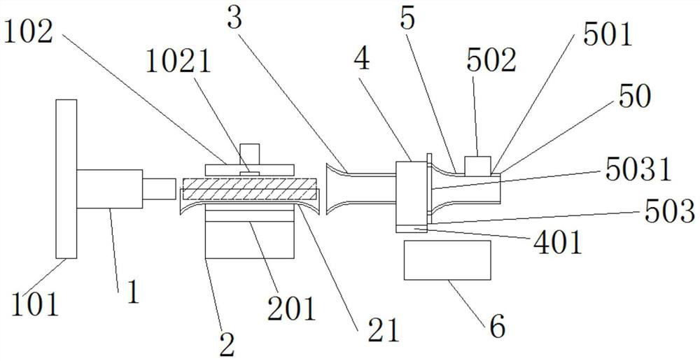
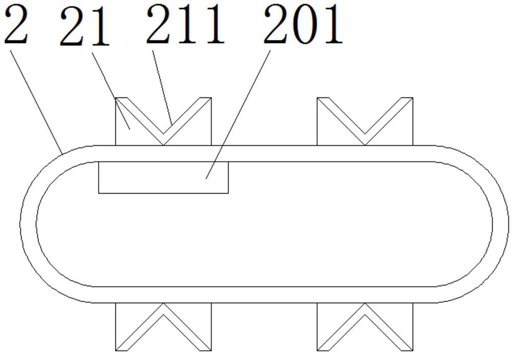
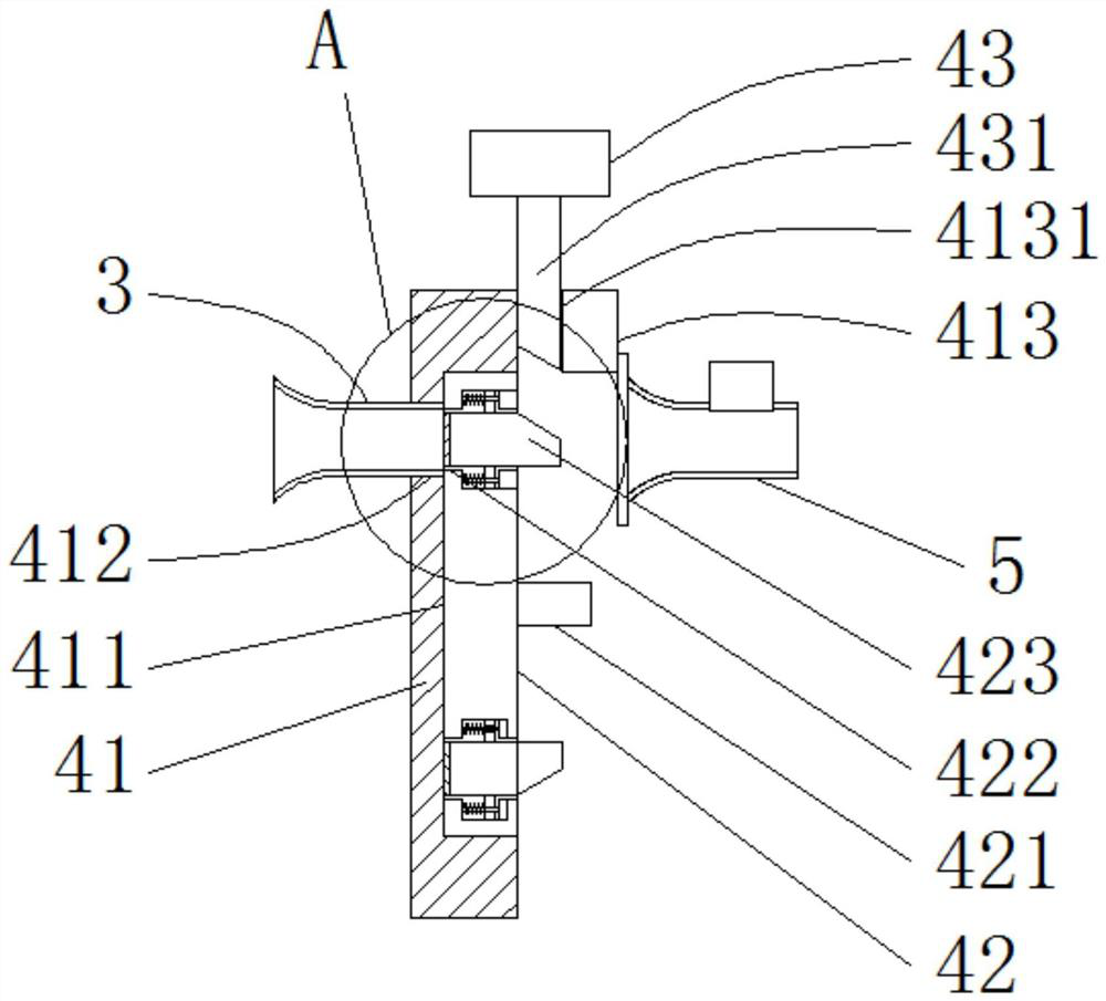
[0019] refer to figure 1 , figure 2 , image 3 , Figure 4 , Figure 5, a tooth bar marking machine of the present invention, comprising a hydraulic rod 1, a conveyor belt 2, a pallet 21, a V-shaped groove 211, a feed pipe 3, a marking device 4, and a discharge pipe 5, and the expansion and contraction of the hydraulic rod 1 The end is horizontally arranged straight to the right, and the right side of the hydraulic rod 1 is provided with a conveyor belt 2, the rotation path of the conveyor belt 2 is perpendicular to the hydraulic rod 1, and several pallets 21 are arranged on the outer surface of the conveyor belt 2, and the upper end surface of each pallet 21 is provided with There are V-shaped grooves 211 arranged in a straight line in the left and right directions, and the V-shaped grooves 211 run through the left and right end faces of the supporting plate 21. The telescopic end on the right side of the hydraulic rod 1 is coaxial, the feed pipe 3 is compatible with the...


PUM


Abstract

The gear rack marking machine comprises a hydraulic rod, a conveying belt, supporting plates, a V-shaped groove, a feeding pipe, a marking device and a discharging pipe, the telescopic end of the hydraulic rod is horizontally and linearly arranged rightwards, the conveying belt is arranged on the right side of the hydraulic rod, the rotating path of the conveying belt is perpendicular to the hydraulic rod, and the multiple supporting plates are arranged on the belt face of the outer side of the conveying belt; the upper end face of each supporting plate is provided with a V-shaped groove linearly formed in the left-right direction, the V-shaped grooves penetrate through the left end face and the right end face of the supporting plate, the V-shaped grooves are matched with the hydraulic rods, the right side of the conveying belt is provided with a feeding pipe, the feeding pipe is coaxial with the telescopic ends of the right sides of the hydraulic rods, the feeding pipe is matched with the V-shaped grooves, and the right end of the feeding pipe is provided with a matched marking device. The right side of the marking device is provided with a corresponding discharging pipe. According to the marking device, automation of marking of the threaded rod can be achieved, the manpower requirement is lowered, and the production efficiency is improved.

Description

【Technical field】 [0001] The invention relates to the technical field of marking machines, in particular to the technical field of a tooth bar marking machine. 【Background technique】 [0002] Tooth bar is Yazi, also known as lead screw, which is the name of furniture parts in Ming and Qing Dynasties. It generally refers to the parts connected between the two legs under the surface frame. The furniture with waist is the main connecting part below the waist. Other parts are generally renamed tooth strips. In addition, they are also used in construction and are most used for decoration. The tooth bar needs to be marked on the tooth bar during the production process, and the existing tooth bar requires a lot of manpower during the marking process, and the efficiency is low. 【Content of invention】 [0003] The purpose of the present invention is to solve the problems in the prior art, and propose a tooth bar marking machine, which can realize the automation of tooth bar markin...

Claims


Application Information

Patent Timeline
Patent Type & Authority Applications(China)
IPC IPC(8): B44B5/00B44B5/02
CPCB44B5/0052B44B5/02B44B5/022
Inventor 唐凯杰
Owner 浙江摩根兄弟科技有限公司
Why Eureka
Try Eureka