Aluminum alloy smelting degassing equipment and degassing method thereof

A degassing equipment and aluminum alloy technology, applied in the field of alloy refining, can solve the problems of trachoma and pores, degassing troubles, uniform distribution of bubbles, etc., and achieve the effect of easy removal and processing

Inactive Publication Date: 2022-03-08
钱军
View PDF0 Cites 3 Cited by
  • Summary
  • Abstract
  • Description
  • Claims
  • Application Information

AI Technical Summary

Problems solved by technology

[0003] During the aluminum alloy casting process, it is necessary to use degassing equipment to discharge the hydrogen and oxygen in the aluminum liquid from the aluminum liquid, so as to avoid the hydrogen and oxygen placed in the aluminum liquid, resulting in aluminum alloy casting, the texture contains For quality problems such as trachoma and pores, for this problem, at present, the degassing operation is mostly carried out based on the gas degassing method. This operation is mainly to blow inert gas into the melt, and then use the principle of partial pressure inside and outside the bubble to degas. In fact, it is When the hydrogen partial pressure inside the bubble is zero, the hydrogen will automatically diffuse to the bubble. The principle is to remove hydrogen first, and then use the principle of oxidation to remove oxygen. At present, when injecting gas, it is difficult to evenly distribute and integrate the bubbles into the melt only by stirring. Therefore, based on the above-mentioned problems, there is an urgent need for a method to control the size of the bubbles and evenly distribute the bubbles. Degassing equipment to solve the current problem of degassing

Method used


Image

  • Aluminum alloy smelting degassing equipment and degassing method thereof
  • Aluminum alloy smelting degassing equipment and degassing method thereof
  • Aluminum alloy smelting degassing equipment and degassing method thereof

Examples


Embodiment 1

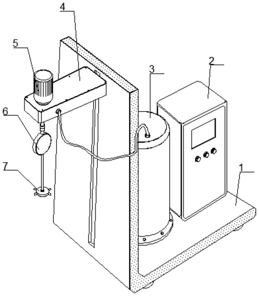
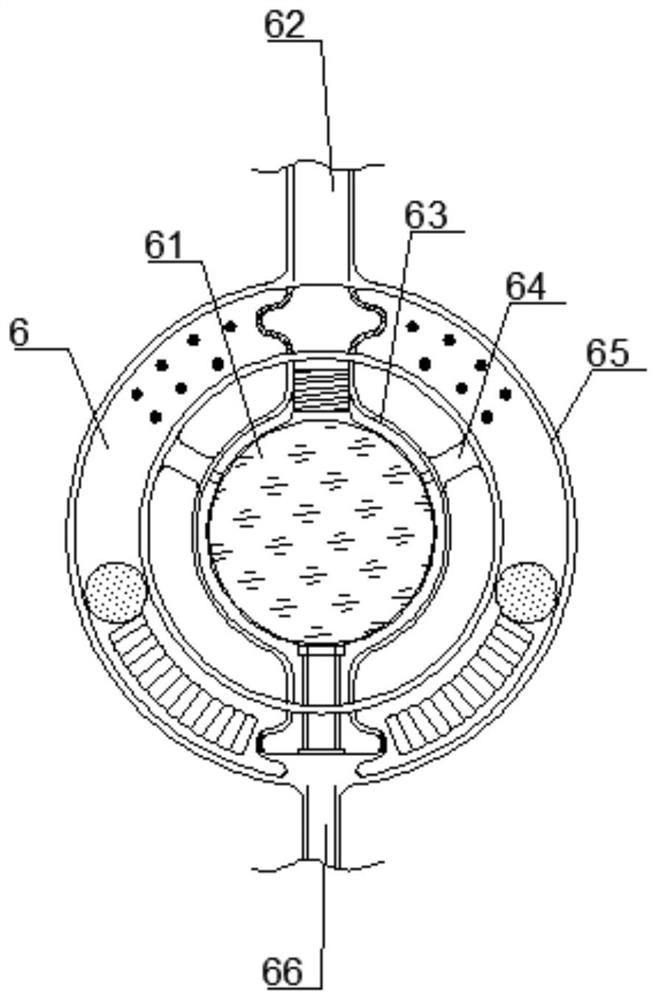
[0030] like Figure 1-2 As shown, the aluminum alloy smelting and degassing equipment includes an L-shaped frame 1 and a track, the side wall of the L-shaped frame 1 is provided with a track, the outer side of the track is provided with a beam 4, and the slider at the beam 4 is inserted into the track; the top of the beam 4 is inserted into the track; A drive unit 5 is fixed, and the drive shaft at the drive unit 5 is protruding relative to the bottom end of the beam 4; a gas treatment device 6 is arranged below the beam 4, and the gas treatment device 6 includes a vibration assembly 65, and a vibration assembly 65 is provided below the transmission shaft. , the top of the vibration assembly 65 is vertically fixed with an inlet pipe 62, and the inlet pipe 62 is connected with the transmission shaft through a coupling; the inner side of the vibration assembly 65 is provided with an annular casing 63, and the two extending ends of the annular casing 63 are connected to the vibrat...

Embodiment 2

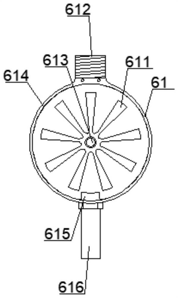
[0035] like figure 2 , 3 As shown in and 5, the aluminum alloy smelting and degassing equipment, the bubble generator 61 includes an impeller 611, a shunt 612, a mandrel 613, a round box 614, a socket 615 and a cannula 616, and the annular casing 63 is sleeved with a round box 614, An annular gap is formed between the outer wall of the round box 614 and the inner wall of the annular casing 63; the upper end of the round box 614 is fixedly connected with a shunt pipe 612, and the shunt pipe 612 is inserted into the overhanging end set above the annular casing 63; the bottom end of the round box 614 penetrates through A socket 615 is embedded, and an intubation tube 616 is sleeved and fixed at the protruding head of the socket 615. The intubation tube 616 is inserted into the protruding end provided below the annular housing 63, and the outer wall of the intubation tube 616 protrudes out relative to the annular housing 63. The inner wall of the end is in the shape of a gap; an...

Embodiment 3

[0039] like Figure 2-4 As shown, the aluminum alloy smelting and degassing equipment, the vibration assembly 65 includes a convex point 651, an upper receiving pipe 652, an outer convex head 653, an annular box 654, a spring 655, a lower receiving pipe 656, a convex head 657 and a small ball 658. 62 is connected with the annular box body 654, an upper receiving pipe 652 is arranged in the annular box body 654 below the inlet pipe 62, and the upper port of the upper bearing pipe 652 is connected with the lower port of the inlet pipe 62; the side wall of the upper bearing pipe 652 is symmetrical The outer convex head 653 is connected, and the outside of the outer convex head 653 is connected with a number of convex points 651 at the inner wall of the annular box body 654; A lower receiving pipe 656 is provided, and the lower port of the lower receiving pipe 656 is connected to the upper port of the row pipe 66; A spring 655 is arranged symmetrically inside, and one end of the ...


PUM


Abstract

The invention provides aluminum alloy smelting degassing equipment and a degassing method thereof, and relates to the field of alloy refining, the aluminum alloy smelting degassing equipment comprises an L-shaped frame and a track, the track is arranged on the side wall of the L-shaped frame, a cross beam is arranged on the outer side of the track, and a sliding block at the cross beam is inserted into the track; a driving unit is fixed at the top end of the cross beam; a transmission shaft at the driving unit extends outwards relative to the bottom end of the cross beam; a gas treatment device is arranged below the cross beam and comprises a vibration assembly, the vibration assembly is arranged below the transmission shaft, an inlet pipe is vertically fixed to the top end of the vibration assembly, and the inlet pipe is connected with the transmission shaft through a coupler; the annular shell is arranged on the inner side of the vibration assembly, tiny bubbles are formed in molten aluminum, inert gas is evenly filled into the molten aluminum during slow rotation of the graphite rotor, and then wide-range fine treatment is conducted on hydrogen and oxygen.

Description

technical field [0001] The invention relates to the field of alloy refining, in particular to aluminum alloy smelting and degassing equipment and a degassing method thereof. Background technique [0002] The alloy liquid in the production process of die-casting parts needs to be refined. The adsorption refining method of die-casting aluminum alloy liquid mainly includes the methods of introducing nitrogen, argon, chlorine, mixed gas refining and using chloride salt refining. Blow in gas or react with the alloy liquid by adding a solvent to the die-casting aluminum alloy liquid to obtain hydrogen-free bubbles, and then use these small bubbles to adsorb hydrogen and oxidized inclusions during the floating process, and entrain them to the die-casting alloy liquid level to achieve removal. Gas and slag. [0003] In the process of aluminum alloy casting, it is necessary to use degassing equipment to discharge the hydrogen and oxygen in the aluminum liquid from the aluminum liqui...

Claims


Application Information

Patent Timeline
Patent Type & Authority Applications(China)
IPC IPC(8): C22C1/06C22C21/00
CPCC22C1/06C22C21/00
Inventor 钱军
Owner 钱军
Why Eureka
Try Eureka