
Smoke near-zero-emission system of coal-fired power plant

A near-zero emission, coal-fired power plant technology, applied in gas treatment, separation methods, lighting and heating equipment, etc., can solve problems such as flue gas pollutants, and achieve the goal of reducing flue gas pollution, improving quality of life, and simplifying installation processes. Effect

Active Publication Date: 2017-08-22
浙江菲达环保科技股份有限公司
View PDF3 Cites 0 Cited by
  • Summary
  • Abstract
  • Description
  • Claims
  • Application Information

AI Technical Summary

Problems solved by technology

[0003] The technical problem to be solved by the present invention is to provide a coal-fired power plant flue gas near-zero emission system to solve the problem of pollutants in existing flue gas emissions

Method used


Image

  • Smoke near-zero-emission system of coal-fired power plant
  • Smoke near-zero-emission system of coal-fired power plant
  • Smoke near-zero-emission system of coal-fired power plant

Examples


Embodiment 1

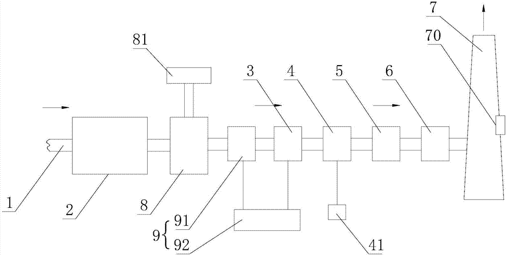
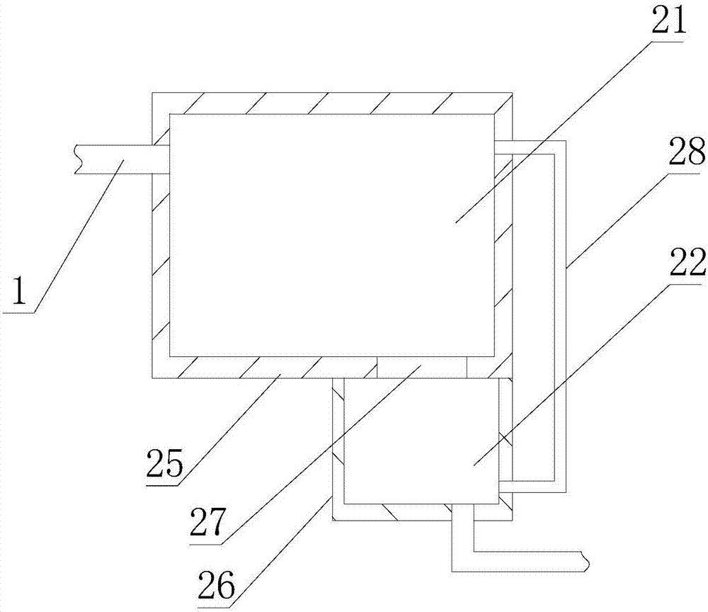
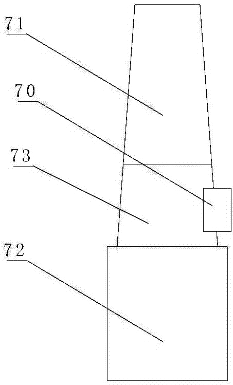
[0021] Such as figure 1 , figure 2 , image 3 As shown, a coal-fired power plant flue gas near-zero emission system includes a discharge pipe 1 for flue gas discharge, and the discharge pipe 1 is sequentially provided with a denitrification device 2 and an electrical discharge pipe 1 along the exhaust direction of the discharge pipe 1. Dust collector 3, wet desulfurization device 4, wet electrostatic precipitator 5, flue gas reheating device 6 and chimney 7; denitrification device 2 is provided with a first processing chamber 21 and a second processing chamber 22, and the first processing chamber 21 is equipped with There is a reducing agent, an oxidation catalyst with Hg is arranged in the second processing chamber 22, and a return pipe 28 is provided on the second processing chamber 22 and the first processing chamber 22; The pipe 1 is provided with a cooling device 8 for reducing the temperature of the flue gas, and the cooling device 8 is connected with a heat exchange ...

Embodiment 2

[0025] A coal-fired power plant flue gas near-zero emission system as described in Embodiment 1, this embodiment has the following differences: Figure 4 As shown, the discharge pipe 1 between the denitrification device 2 and the electrostatic precipitator 3 is provided with a base spraying device 10, and the base spraying device 10 is connected with a supply system 11, and the supply system 11 sprays into the flue gas used to adsorb SO in flue gas 3 base, can effectively remove SO in flue gas 3 , and through the system to realize the feeding treatment of the base spraying device, the continuous spraying of the base to the flue gas is realized.

[0026] When used, such as figure 1 As shown, the direction indicated by the arrow is the direction of flue gas discharge. The flue gas enters the denitrification device 2 through the discharge pipe 1, and the flue gas is sequentially processed by the first processing chamber 21 and the second processing chamber 22, and passes throug...


PUM


Abstract

The invention relates to a smoke near-zero-emission system of a coal-fired power plant. The smoke near-zero-release emission system comprises a discharging pipe, wherein the discharging pipe is successively provided with a denitration apparatus, an electric dust collector, a wet-method desulphurization apparatus, a wet-type electric dust collector, a smoke reheating apparatus and a chimney; the denitration apparatus is provided with a first treatment cavity and a second treatment cavity, the first treatment cavity is internally provided with a reducing agent, and the second treatment cavity is internally provided with an oxidized catalyst with Hg; and the discharging pipe between the denitration apparatus and the electric dust collector is provided with a cooling apparatus for lowering the temperature of smoke. The smoke near-zero-emission system has the advantages that the smoke is successively treated by virtue of the denitration apparatus, the electric dust collector, the wet-method desulphurization apparatus and the wet-type electric dust collector, main pollutants in the smoke can be gradually removed, and the smoke is then heated by virtue of the smoke reheating apparatus, so that the visual pollution is eliminated; and finally the smoke is discharged by virtue of the chimney, and the near-zero emission of the smoke is realized, so that the content of pollutants in the smoke is greatly reduced, the smoke pollution is reduced, and the living quality is improved.

Description

technical field [0001] The invention relates to a near-zero emission system for flue gas in a coal-fired power plant. Background technique [0002] Coal-fired power plants are easy to discharge flue gas during the production process, and the flue gas contains PM, SOX, NOX, Hg and other pollutants. The existing flue gas treatment system adopts conventional flue gas treatment system, including the treatment of a pollution The single equipment of the material can only remove one pollutant in the flue gas, but cannot achieve near-zero discharge of pollutants, causing the pollutants in the flue gas to seriously exceed the standard, which is likely to have a serious impact on people's lives and health. Contents of the invention [0003] The technical problem to be solved by the present invention is to provide a coal-fired power plant flue gas near-zero emission system to solve the problem of pollutants in the existing flue gas emission. [0004] In order to solve the above-ment...

Claims


Application Information

Patent Timeline
Patent Type & Authority Applications(China)
IPC IPC(8): B01D53/75B01D53/64B01D53/56B01D53/50B01D50/00F23J15/02
CPCB01D50/00B01D53/50B01D53/56B01D53/64B01D53/75F23J15/02F23J15/022B01D2258/0283
Inventor 郦建国刘含笑姚宇平赵琳杜依倩何德源杨浩锋
Owner 浙江菲达环保科技股份有限公司
Learn More