Method and device for testing dynamic speckles in laser display

A technology of laser display and dynamic speckle, which is applied in the direction of measuring devices, optical instrument testing, machine/structural component testing, etc., and can solve problems such as the influence of screen microstructure brightness uniformity

Active Publication Date: 2022-03-08
上海唯视锐光电技术有限公司
View PDF7 Cites 1 Cited by
  • Summary
  • Abstract
  • Description
  • Claims
  • Application Information

AI Technical Summary

Problems solved by technology

[0018] The purpose of the present invention is to overcome the situation that the current laser speckle test method is easily affected by the screen microstructure, image pixel unit structure, and brightness uniformity, and provide a more versatile and more accurate laser display dynamic speckle test method and its test device

Method used


Image

  • Method and device for testing dynamic speckles in laser display
  • Method and device for testing dynamic speckles in laser display
  • Method and device for testing dynamic speckles in laser display

Examples


Embodiment 1

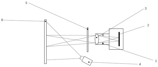
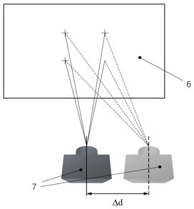
[0080] Example 1, such as Figure 2-4 As shown, it is composed of a screen 6, a laser display device 4, a test device 7, a mobile device (not shown in the figure), a computer (not shown in the figure), and the test device includes: an optical lens 3, an aperture 1, The optical filter 5, the image acquisition unit 2, the test device is connected to the computer by signal, and the image taken by the image acquisition unit is transmitted to the computer. The calculation formula is stored in the computer, and the computer controls the image acquisition unit to take pictures of the speckle pattern. The front of the acquisition unit is arranged with diaphragm 1, optical lens 3, and optical filter 5 in order from near to far. The light projected by the laser display device 4 is projected onto the screen 6 and then reflected through the optical filter, optical lens, and optical diaphragm to enter the image. The acquisition unit, the mobile device enables the image acquisition unit ...

Embodiment 2

[0100] Example 2, such as Figure 5 As shown, the moving device is a swingable smooth glass sheet 8, which is located between the filter and the screen. The smooth glass sheet is swung at a small angle to change the incident light entering the diaphragm so as to achieve the incident light after a small displacement of the image acquisition unit. Same effect for ray shifting.

[0101] The plane where the swing axis of the smooth glass sheet is located is parallel to the screen, and the smooth glass sheet is at different positions centered on the swing axis when the image acquisition unit collects images twice. The plane where the swing axis is located is parallel to the screen, and the swing axis can theoretically be any straight line in the plane. The swing angle of the smooth glass sheet is <20°, and the swing angle should be reduced as much as possible, and the swing angle selected in this example is ±8°.

[0102] The specific implementation steps are as follows: wh...


PUM


Abstract

A method for measuring dynamic speckles in laser display is characterized in that a test method and steps are as follows: a tested image is projected to a screen with a zone bit, the shooting direction of test equipment is perpendicular to the screen, focusing is performed until the image is clear, a first image is collected, the vertical distance between the test equipment and the screen is kept unchanged, and a second image is collected; after an image formed by the screen image on the test device is moved by using a moving device, the test device acquires a second image, so that the image acquisition unit acquires two images with the same test area and different observation positions, and the two images at least have a common test area with a flag bit as a boundary; and carrying out image correlation processing calculation on the two pictures to finally obtain the dynamic speckle contrast. Compared with a speckle contrast static testing method used in the industry at present, the dynamic speckle contrast obtained by the method is higher in accuracy, and the method can be widely applied to speckle measurement of laser display products such as laser televisions, laser projectors and laser cinemas.

Description

technical field [0001] The invention relates to an evaluation and testing method, which belongs to the field of laser display performance testing, in particular to a testing method and a testing device for dynamic speckle in laser display. Background technique [0002] Laser display refers to the display technology that uses laser light as the light source. Compared with other display technologies, laser display has the largest color expression space, and its color gamut coverage can theoretically reach more than 90% of the color space that can be recognized by human eyes. It also has the advantages of high energy utilization rate, environmental protection, long life, and wide product coverage. It has become one of the most promising display technologies, and the market is also showing a trend of rapid growth. [0003] As a narrow-band light source, laser has high coherence. When the laser is reflected by a rough reflective surface (or passes through a scatterer), the reflec...

Claims


Application Information

Patent Timeline
Patent Type & Authority Applications(China)
IPC IPC(8): G01M11/02
CPCG01M11/0257
Inventor 舒伟许仁杰刘默晗李清明张晓峰刘红王蔚生
Owner 上海唯视锐光电技术有限公司
Why Eureka
Try Eureka