Laser Scanning Projection System with Reduced Speckle Contrast and Speckle Contrast Reducing Method

a laser scanning and projection system technology, applied in projectors, color television details, instruments, etc., can solve the problems of reducing the speckle contrast of the laser scanning projection system, affecting the quality of the laser scanning image, so as to reduce the speckle contrast

Inactive Publication Date: 2014-01-02
LITE ON TECH CORP
View PDF2 Cites 11 Cited by
  • Summary
  • Abstract
  • Description
  • Claims
  • Application Information

AI Technical Summary

Benefits of technology

[0012]A further embodiment of the present invention provides a laser scanning projection system with reduced speckle contrast. The laser scanning projection system includes a projection surface, an illumination unit, a scanning mirror module, and a driver. The illumination unit is used for emitting a laser beam along an optical path. The scanning mirror module is used for projecting the laser beam on the projection surface according to a scanning trajector

Problems solved by technology

However, due to the narrow spectrum and the coherent property of the laser source, speckle arises when the images are created.
When a coherent beam from the laser source is projected onto a randomly-diffusing rough surface (e.g. a wall), a portion of the reflected beam may constructively or destructively interfere with another portion of the reflected beam.
Moreover, the constructive interference and the destructive interference of the reflected beam may result in randomly distributed bright/dark fringes in the space.
However, it is very complicated to process the image.
However, the process of assembli

Method used


Image

  • Laser Scanning Projection System with Reduced Speckle Contrast and Speckle Contrast Reducing Method
  • Laser Scanning Projection System with Reduced Speckle Contrast and Speckle Contrast Reducing Method
  • Laser Scanning Projection System with Reduced Speckle Contrast and Speckle Contrast Reducing Method

Examples


first embodiment

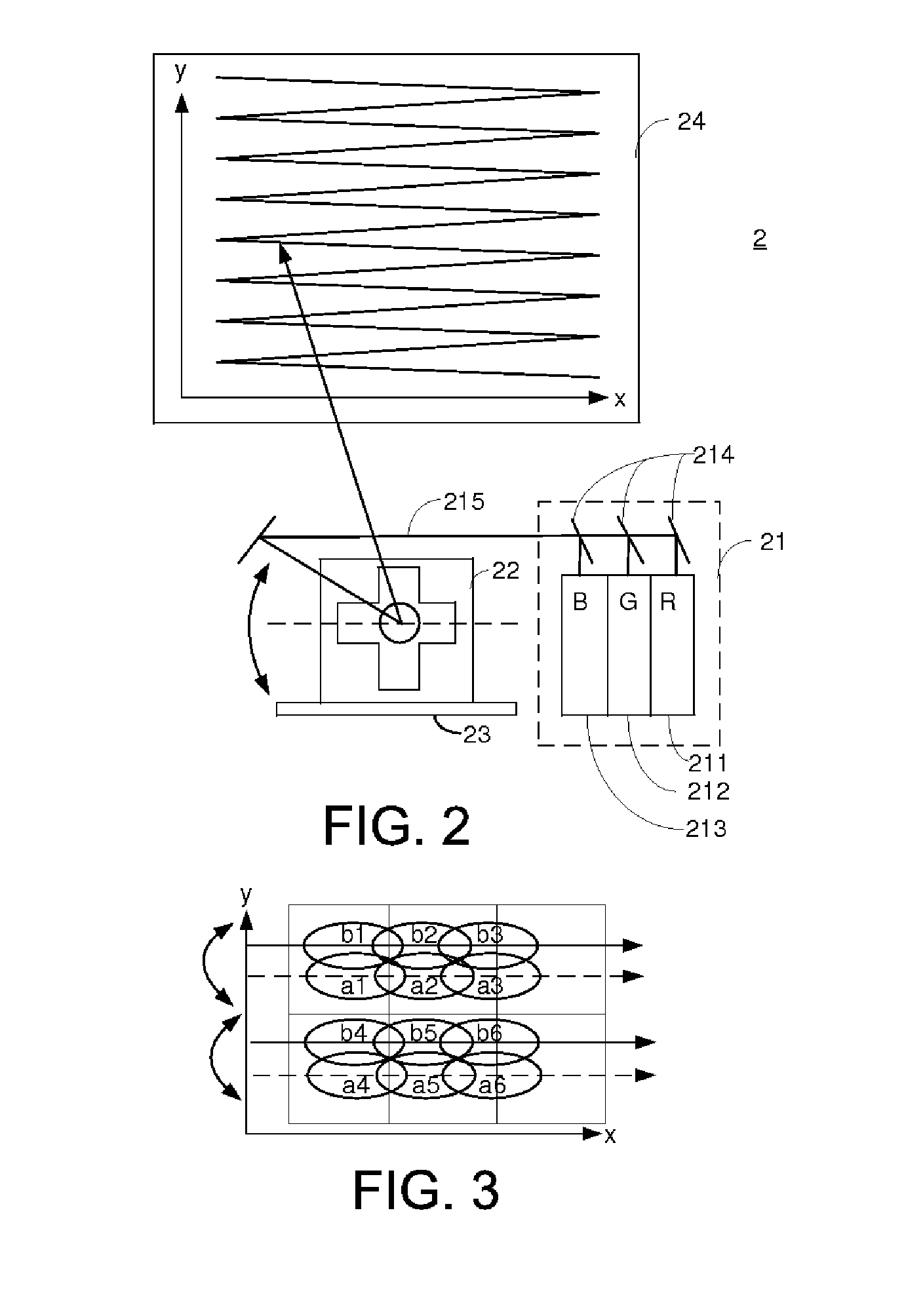
[0022]FIG. 2 schematically illustrates the architecture of a laser scanning projection system with reduced speckle contrast according to the present invention. As shown in FIG. 2, the laser scanning projection system 2 comprises an illumination unit 21, a scanning mirror module 22, a tilt angle adjustable element 23, and a projection surface 24.

[0023]The illumination unit 21 comprises a plurality of laser sources 211, 212, 213 and one or more optical alignment elements 214. In this embodiment, the laser sources of the illumination unit 21 comprises a red laser source 211, a green laser source 212, and a blue laser source 213, as are respectively indicated by “R”, “G,” and “B” in FIG. 2. In this embodiment, the illumination unit 21 comprises three optical alignment elements 214. Examples of the optical alignment elements 214 include but are not limited to dichroic mirrors. By the optical alignment devices 214, the red beam, the green beam and the blue beam from the red laser source 2...

second embodiment

[0033]FIG. 5 schematically illustrates the architecture of a laser scanning projection system with reduced speckle contrast according to the present invention. As shown in FIG. 5, the laser scanning projection system 5 comprises an illumination unit 51, a scanning mirror module 52, a driver 53, and a projection surface 54.

[0034]The illumination unit 51 comprises a plurality of laser sources 511, 512, 513 and one or more optical alignment elements 514. In this embodiment, the laser sources of the illumination unit 51 comprises a red laser source 511, a green laser source 512, and a blue laser source 513, as are respectively indicated by “R”, “G,” and “B” in FIG. 5. In this embodiment, the illumination unit 51 comprises three optical alignment elements 514. Examples of the optical alignment elements 514 include but are not limited to dichroic mirrors. By the optical alignment devices 514, the red beam, the green beam and the blue beam from the red laser source 511, the green laser sou...


PUM


Abstract

A speckle contrast reducing method for a laser scanning projection system includes the following steps. Firstly, a laser beam is provided. The laser beam is projected on a projection surface according to a first scanning trajectory, thereby generating a first image frame. Sequentially, the laser beam is projected on the projection surface according to a second scanning trajectory, thereby generating a second image frame at an image refresh rate. Moreover, the second scanning trajectory of the second image frame is shifted by a displacement from the first scanning trajectory of the first image frame along a slow-axis direction.

Description

FIELD OF THE INVENTION[0001]The present invention relates to a laser scanning projection system, and more particularly to a laser scanning projection system with reduced speckle contrast. The present invention relates to a speckle contrast reducing method for a laser scanning projection system.BACKGROUND OF THE INVENTION[0002]As known, a laser source has a narrower emission spectrum than a LED source. The use of the laser source in a projection system is able to result in better color purity and create vivid images with extensive color coverage. However, due to the narrow spectrum and the coherent property of the laser source, speckle arises when the images are created. When a coherent beam from the laser source is projected onto a randomly-diffusing rough surface (e.g. a wall), a portion of the reflected beam may constructively or destructively interfere with another portion of the reflected beam. Consequently, the intensity of the reflected beam fluctuates. Moreover, the construct...

Claims


Application Information

Patent Timeline
IPC IPC(8): G03B21/28G03B21/14
CPCG02B26/0833G02B26/101G02B27/48G03B21/2033G03B21/208G03B33/06H04N9/3129
Inventor TSAI, FU-JILIN, WEI-CHIHLIN, WEN-LUNG
Owner LITE ON TECH CORP
Why Eureka
Try Eureka