
Real-time industrial diagnosis method

A diagnostic method and industrial technology, applied in the direction of instruments, computer control, simulators, etc., can solve problems such as time-consuming, labor-intensive, lack, inability to monitor and feedback

Pending Publication Date: 2022-03-08
江苏爱森思电气有限公司
View PDF0 Cites 0 Cited by
  • Summary
  • Abstract
  • Description
  • Claims
  • Application Information

AI Technical Summary

Problems solved by technology

Controlled equipment such as valves need to monitor their pressure, angle signals, and displacement signals at the same time. Today, there is no effective real-time monitoring device, so it is impossible to monitor and feedback problems in continuous production in real time. When problems occur in the production line In this case, it can only be repaired after the machine is shut down and disassembled to confirm the problem, which is time-consuming and labor-intensive.

Method used


Image

  • Real-time industrial diagnosis method
  • Real-time industrial diagnosis method
  • Real-time industrial diagnosis method

Examples


Embodiment 1

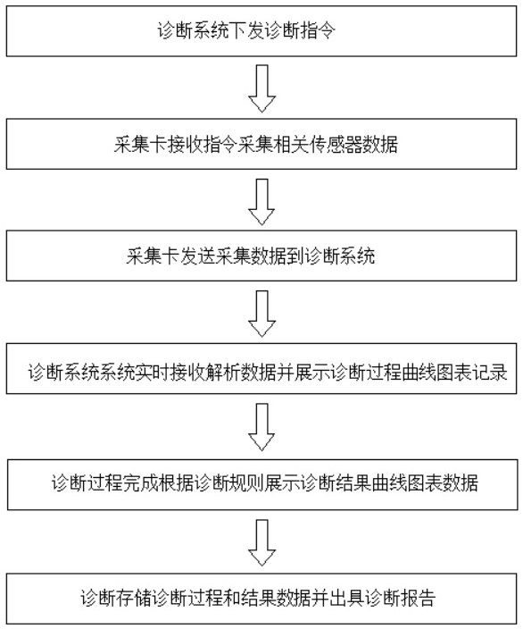
[0038] join figure 1 and figure 2 , the present invention relates to a real-time industrial diagnosis method,

[0039] After the diagnostic program issues diagnostic instructions, multiple signal sensors installed on the controlled equipment will input the sampling signals of diagnostic parameters (such as pressure signals, angle signals, displacement signals, etc.) collected into the sampling unit, and the sampling unit will convert the sampling signals into After the digital signal is transmitted to the main control MCU, the main control MCU transmits the signal to the industrial computer for diagnosis, analysis and processing through the network, and the industrial computer transmits the control signal to the main control MCU through the network according to the analysis and processing results, and the main control MCU outputs the signal through the analog quantity. The module transmits the control signal to the control unit of the controlled equipment, thereby realizing ...

Embodiment 2

[0051] The invention relates to a real-time industrial diagnosis method,

[0052] After the diagnostic program issues the diagnostic command, multiple signal sensors installed on the controlled device input the sampling signal into the sampling unit, the sampling unit converts the sampling signal into a digital signal and transmits it to the main control MCU, and the main control MCU diagnoses and analyzes the digital signal After processing, the main control MCU sends the corresponding generated control signal to the control unit of the controlled device through the analog output module according to the processing result.

[0053] see figure 1 , an industrial diagnostic system, the first and second embodiments above can be realized based on a diagnostic system, the system includes a sampling unit and a processing unit installed on a circuit board, and the circuit board is installed in the housing of the acquisition card :

[0054] The above-mentioned sampling unit converts ...


PUM


Abstract

According to the real-time industrial diagnosis method, a plurality of signal sensors installed on controlled equipment input sampling signals into a sampling unit, the sampling unit converts the sampling signals into digital signals and then transmits the digital signals to a master control MCU, and the master control MCU transmits the signals to an industrial personal computer through a network for diagnosis, analysis and processing and sends the signals to the industrial personal computer. The industrial personal computer transmits a control signal to the master control MCU through a network according to an analysis processing result, and the master control MCU transmits the control signal to a control unit of the controlled equipment through the analog quantity output module. According to the real-time industrial diagnosis method, signals of controlled equipment can be collected in real time, and uninterrupted monitoring is achieved.

Description

technical field [0001] The invention relates to a real-time industrial diagnosis method, which belongs to the technical field of industrial automation. Background technique [0002] At present, with the advancement of the Industrial Internet of Things, more and more traditional industrial fields have begun to introduce automation control. In the process of automation control, a variety of sensors are needed to monitor the equipment in real time, so that it can be in a safe and controllable working state. Down. Controlled equipment such as valves need to monitor their pressure, angle signals, and displacement signals at the same time. Today, there is no effective real-time monitoring device, so it is impossible to monitor and feedback problems in continuous production in real time. When problems occur in the production line Sometimes it can only be repaired after shutting down and dismantling to confirm the problem point, which is time-consuming and labor-intensive. For thi...

Claims


Application Information

Patent Timeline
Patent Type & Authority Applications(China)
IPC IPC(8): G05B19/042
CPCG05B19/0423G05B2219/24215
Inventor 陆诚胡晓刚沈勇赵坚陆鸣峰
Owner 江苏爱森思电气有限公司
Learn More