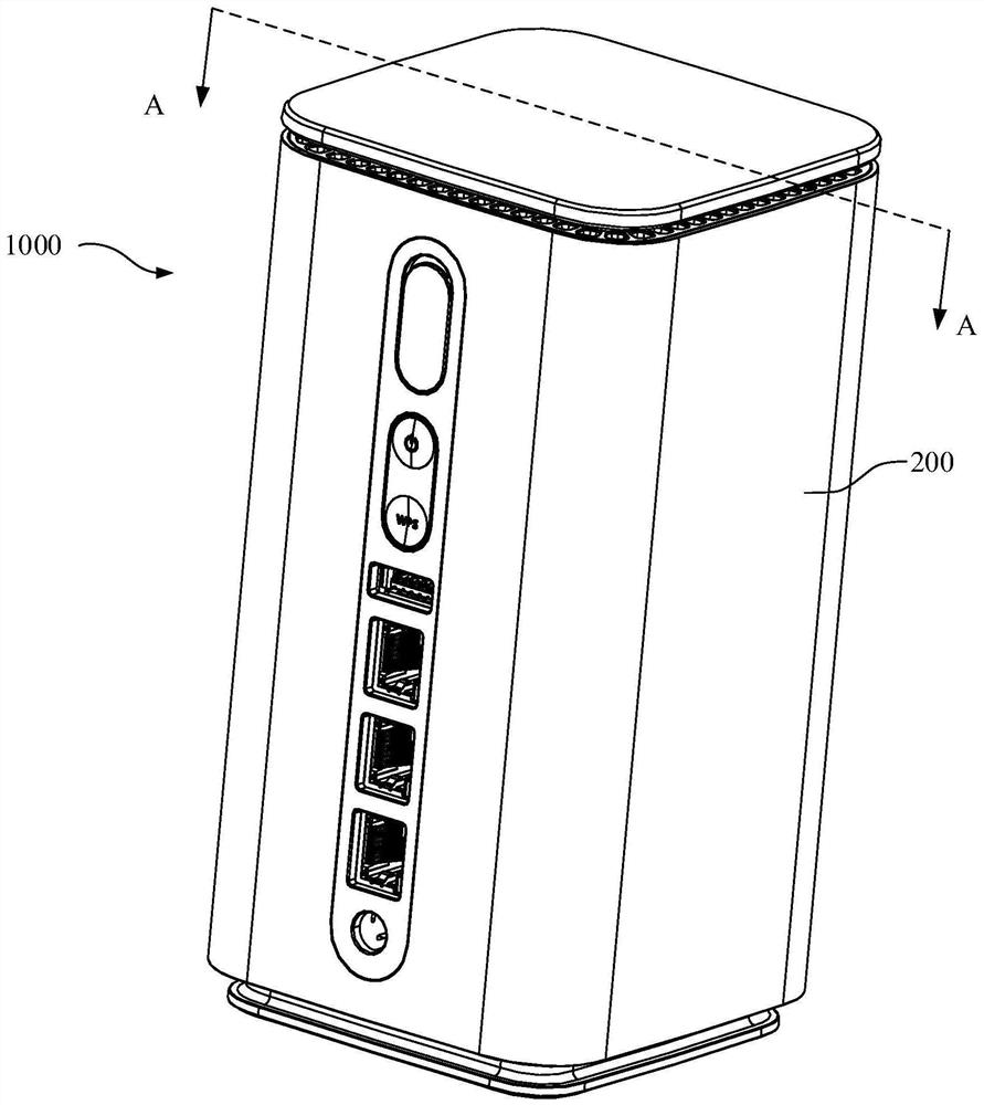
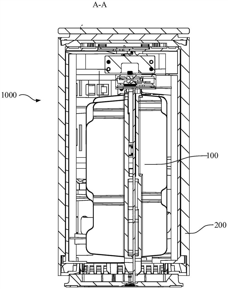
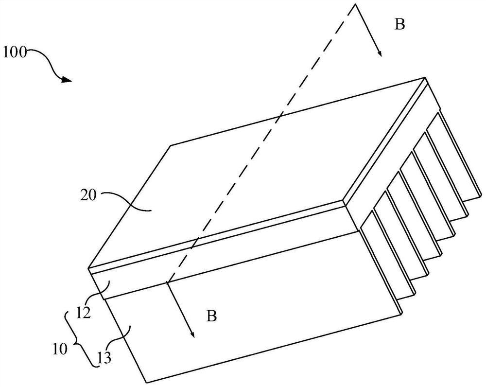
Chip heat dissipation structure and electronic equipment

A chip heat dissipation and chip technology, which is applied in the field of chip heat dissipation structure and electronic equipment, can solve the problems of difficult heat conduction of chips, the risk of overheating of working temperature, and the risk of overtemperature, so as to improve the heat dissipation effect, reduce the impact, and absorb effect of tolerance

Pending Publication Date: 2022-03-08
GUANGDONG OPPO MOBILE TELECOMM CORP LTD
View PDF0 Cites 1 Cited by
  • Summary
  • Abstract
  • Description
  • Claims
  • Application Information

AI Technical Summary

Problems solved by technology

[0002] With the advent of the 5G communication era, the power consumption density of electronic devices such as routers is increasing rapidly, resulting in severe over-temperature risks for the operating temperature of related electronic devices
Due to the existence of a large gap between the chip and the heat sink due to the existence of tolerances, the interface material is usually used to directly fill the gap at present, but the thermal conductivity of the interface material is usually small, which makes it difficult for the heat on the chip to be effectively conducted and there is a risk of overheating

Method used


Image

  • Chip heat dissipation structure and electronic equipment
  • Chip heat dissipation structure and electronic equipment
  • Chip heat dissipation structure and electronic equipment

Examples


Embodiment Construction

[0023] The application will be described in further detail below in conjunction with the accompanying drawings and embodiments. In particular, the following examples are only used to illustrate the present application, but not to limit the scope of the present application. Likewise, the following embodiments are only some of the embodiments of the present application but not all of them, and all other embodiments obtained by those skilled in the art without creative efforts fall within the protection scope of the present application.

[0024] Reference herein to an "embodiment" means that a particular feature, structure, or characteristic described in connection with the embodiment can be included in at least one embodiment of the present application. The occurrences of this phrase in various places in the specification are not necessarily all referring to the same embodiment, nor are separate or alternative embodiments mutually exclusive of other embodiments. It is understoo...


PUM


Abstract

The invention relates to a chip heat dissipation structure and electronic equipment. The chip heat dissipation structure comprises a radiator, a circuit board, a chip and a heat conduction assembly. The radiator comprises a heat dissipation plate, the circuit board and the heat dissipation plate are arranged in parallel at an interval, the chip is attached to the surface, facing the heat dissipation plate, of the circuit board, and the heat conduction assembly is located between the chip and the heat dissipation plate; wherein the heat conduction assembly comprises a first boundary layer, a heat sink plate and a second boundary layer which are sequentially stacked, the first boundary layer is located between the heat sink plate and the chip, and the second boundary layer is located between the heat sink plate and the heat dissipation plate. The electronic equipment comprises the chip heat dissipation structure. Through the mode, the heat resistance of the heat conduction assembly can be reduced, the heat dissipation effect of the chip is further improved, the tolerance between the chip and the heat dissipation plate can be absorbed, and the influence of the tolerance on heat dissipation is reduced.

Description

technical field [0001] The present application relates to the technical field of electronic equipment, in particular to chip heat dissipation structures and electronic equipment. Background technique [0002] With the advent of the 5G communication era, the power consumption density of electronic devices such as routers has increased rapidly, leading to severe over-temperature risks for the operating temperature of related electronic devices. In order to quickly transfer the heat on the chip on the circuit board to the heat sink, the chip is usually attached directly to the heat sink. Due to the existence of a large gap between the chip and the heat sink due to the existence of tolerances, the interface material is usually used to directly fill the gap at present, but the thermal conductivity of the interface material is usually small, which makes it difficult for the heat on the chip to be effectively conducted and there is a risk of overheating . Contents of the inventi...

Claims


Application Information

Patent Timeline
Patent Type & Authority Applications(China)
IPC IPC(8): H05K1/02H05K1/18H05K7/20
CPCH05K1/0203H05K1/18
Inventor 胡院林
Owner GUANGDONG OPPO MOBILE TELECOMM CORP LTD
Why Eureka
Try Eureka