High-elasticity flame-retardant fiber band glue removing equipment for wind energy cable

A flame-retardant fiber and high-elasticity technology, which is used in the field of high-elasticity flame-retardant fiber belt degumming equipment for wind energy cables, can solve the problem of inability to accurately control the thickness of nylon-based fiber cloth to remove glue, affect degumming and drying, nylon-based fiber cloth. The fluff of the base fiber cloth is disorganized and other problems, so as to save the cleaning work, facilitate degumming and drying, and achieve the effect of neat fluff.

Active Publication Date: 2022-03-11
山东滨澳电线电缆有限公司
View PDF7 Cites 0 Cited by
  • Summary
  • Abstract
  • Description
  • Claims
  • Application Information

AI Technical Summary

Problems solved by technology

[0004] In order to overcome the shortcomings of the disordered fluff on the surface of nylon-based fiber cloth, which affects the subsequent degumming and drying, and the inability to accurately control the thickness of the glue on the surface of nylon-based fiber cloth, the invention provides a high-elastic flame-retardant fiber for wind energy cables With glue removal equipment

Method used


Image

  • High-elasticity flame-retardant fiber band glue removing equipment for wind energy cable
  • High-elasticity flame-retardant fiber band glue removing equipment for wind energy cable
  • High-elasticity flame-retardant fiber band glue removing equipment for wind energy cable

Examples


Embodiment 1

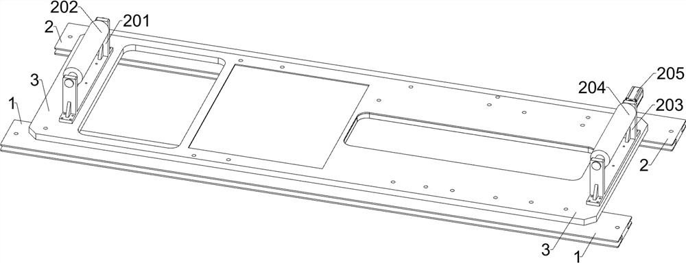
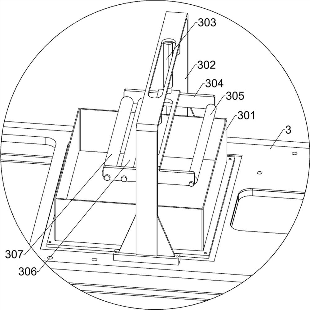
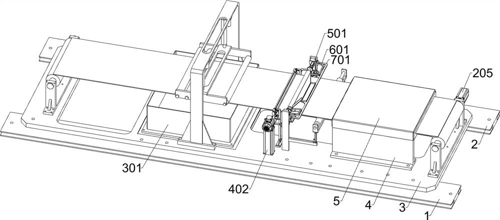
[0033] A kind of high elastic flame retardant fiber tape cleaning equipment for wind energy cables, such as Figure 1-11 As shown, it includes a first bolt base plate 1, a second bolt base plate 2, an installation base plate 3, a fixing frame 4, a dryer 5, a winding unit, a dipping unit, a wrinkle-removing tensioning unit and a glue-removing unit; the first Bolt base plate 1 and second bolt base plate 2 upper surfaces are bolt-connected with installation base plate 3, and installation base plate 3 is provided with the collection area for collecting excess glue; installation base plate 3 upper surface right side is welded with two fixing brackets 4; A dryer 5 is installed on the upper surface of a fixed frame 4; a winding unit is installed on the upper surface of the installation base plate 3; a dipping unit is installed on the left side of the upper surface of the installation base plate 3; ; The glue removal unit is installed in the middle of the upper surface of the installa...

Embodiment 2

[0043] On the basis of Example 1, such as figure 1 and Figure 12 As shown, an edge glue cleaning unit is also included, and an edge glue cleaning unit is installed on the right side of the glue removing unit. Plate 604 and the second cleaning plate 605; two second drive members 503 right sides are respectively fixed with a second connecting frame 601; two second connecting frames 601 opposite sides are respectively fixed with a deflector 604; two The opposite side of the second connecting frame 601 is respectively fixed with a first cleaning plate 603, and the two first cleaning plates 603 are located on the left side of the two deflectors 604; Plate 604, the first cleaning plate 603 at the rear contacts the deflector 604 at the rear; the third connecting frame 602 is connected by bolts between the two third driving parts 504; the third connecting frame 602 is fixed with two front and rear symmetrical The second cleaning plate 605.

[0044] Wherein, the two deflectors 604 ...

Embodiment 3

[0048] On the basis of Example 2, such as figure 1 , Figure 13-14 As shown, it also includes a roller rubber cleaning unit, and the left and right sides of the two T-shaped plates 501 are equipped with a roller rubber cleaning unit, and the roller rubber cleaning unit includes a fourth connecting frame 701, a collection frame 702 and a cleaning frame 703; two The upper left part of the T-shaped plate 501 is bolt-connected with two fourth connecting frames 701, and the middle part of the upper surface of the two fourth connecting frames 701 is fixedly connected with a collection frame 702; the opposite sides of the two fourth connecting frames 701 are respectively welded with a cleaning frame 703.

[0049] When the two glue removal rollers 508 remove excess glue on the surface of the fiber cloth, the cleaned glue remains on the surfaces of the two glue remover rollers 508. The removal thickness of the excess glue on the surface of the fiber cloth by the two glue removal roll...


PUM


Abstract

The invention relates to the field of wind energy, in particular to glue removing equipment for a high-elasticity flame-retardant fiber band for a wind energy cable. The technical problems that fluff on the surface of nylon-based fiber cloth is disordered, subsequent glue removing and drying are affected, and the glue solution removing thickness on the surface of the nylon-based fiber cloth cannot be accurately controlled are solved. According to the technical scheme, the glue removing equipment for the high-elasticity flame-retardant fiber band for the wind energy cable comprises a mounting bottom plate, a winding unit and the like; and a winding unit for conveying and winding nylon-based fiber cloth is mounted on the upper surface of the mounting bottom plate. According to the device, the surface fluff of the nylon-based fiber cloth is tidied, so that the fluff is tidy, later-stage glue removing and drying are facilitated, the thickness of the removed glue solution can be accurately controlled, meanwhile, the glue solution accumulated on the edges of the two sides of the nylon-based fiber cloth is cleaned, the glue solution adhered to the surface of the roller body after the glue solution is cleaned is cleaned, and the quality of the nylon-based fiber cloth is improved. Not only is the thickness of the cleaned glue solution ensured, but also the later manual cleaning work is omitted.

Description

technical field [0001] The invention relates to the field of wind energy, in particular to a glue-removing device for a highly elastic flame-retardant fiber tape for wind energy cables. Background technique [0002] In the prior art, during the process of dipping nylon-based fiber cloth, removing excess glue, and then drying to form a high-elastic flame-retardant fiber tape for wind energy cables, the fuzz on the surface of the nylon-based fiber cloth is disorderly, which affects the subsequent degumming and drying. Dry, resulting in the surface of the highly elastic flame-retardant fiber tape after drying is not smooth enough, affecting the aesthetics and practicability; [0003] Secondly, during the process of removing excess glue, the nylon-based fiber cloth has the problem of wrinkling, which leads to the inability to accurately control the thickness of the removed glue on the surface of the nylon-based fiber cloth, and thus cannot produce high elastic resistance composi...

Claims


Application Information

Patent Timeline
Patent Type & Authority Applications(China)
IPC IPC(8): B05C3/15B05C9/14B05C11/02H01B7/295
CPCB05C3/15B05C9/14B05C11/025B05C11/023H01B7/295
Inventor 谢值杰
Owner 山东滨澳电线电缆有限公司
Why Eureka
Try Eureka