Surface detection device for optical filter product

A surface detection and optical filter technology, applied in the field of optical filter detection, can solve the problems of low efficiency and manpower consumption, and achieve the effects of avoiding losses, saving time and increasing work efficiency

Pending Publication Date: 2022-03-11
六安原景智能科技有限公司
View PDF0 Cites 0 Cited by
  • Summary
  • Abstract
  • Description
  • Claims
  • Application Information

AI Technical Summary

Problems solved by technology

[0004] The purpose of the present invention is to solve the problems of labor-intensive and low efficiency in the prior art, and propose a surface inspection device for optical filter products

Method used


Image

  • Surface detection device for optical filter product
  • Surface detection device for optical filter product
  • Surface detection device for optical filter product

Examples


Embodiment 1

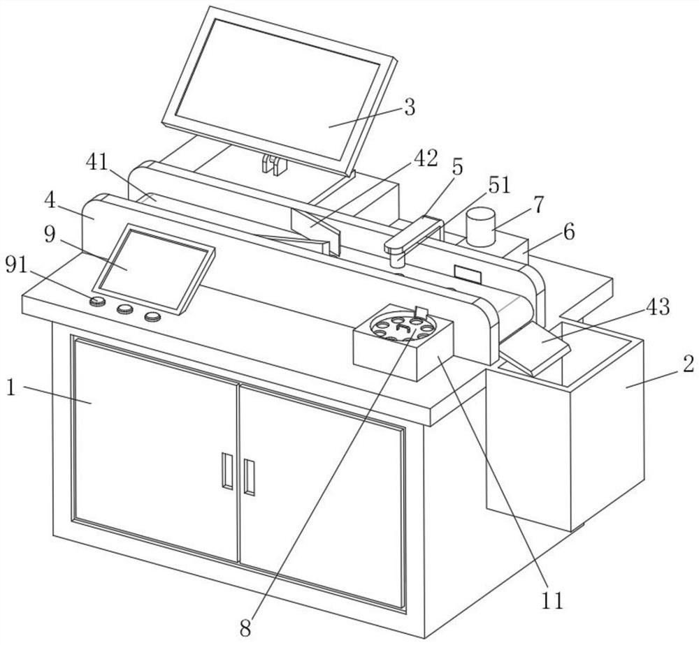
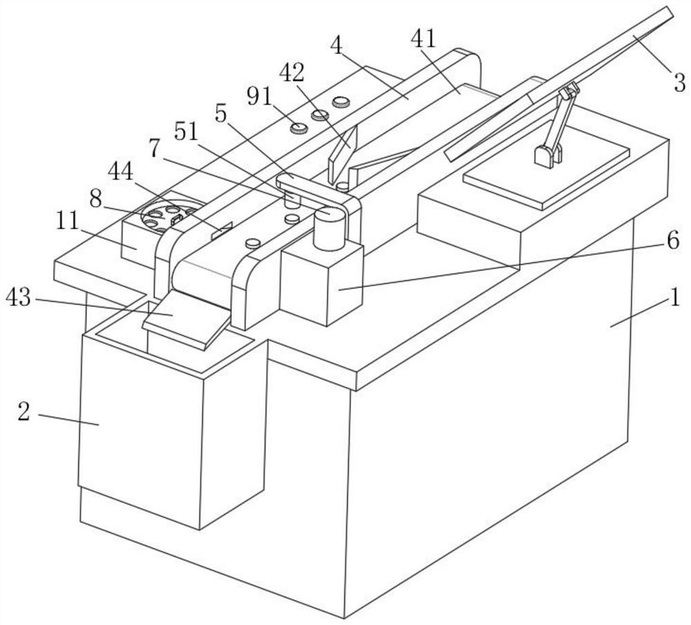
[0031] refer to Figure 1-6 , a surface detection device for optical filter products, including an operating table 1, the upper surface of the operating table 1 is communicated with a protective tube 11, and one side of the operating table 1 is fixedly installed with a defective product collection box 2, for the sorted out The defective products are collected, and the upper surface of the console 1 is fixedly equipped with a display 3 to display the situation on the surface of the optical filter. The upper surface of the console 1 is equipped with a bracket 4, and the opposite surface of the bracket 4 is rotatably connected with a conveyor belt 41 to drive the filter. In order to fix the position of the optical filter in one direction, a slide plate 43 is fixedly installed on one end of the support 4, and the slide plate 43 is arranged in the defective product collection box. 2, a trapezoidal outlet 44 is provided through one side of the bracket 4, which facilitates the remova...

Embodiment 2

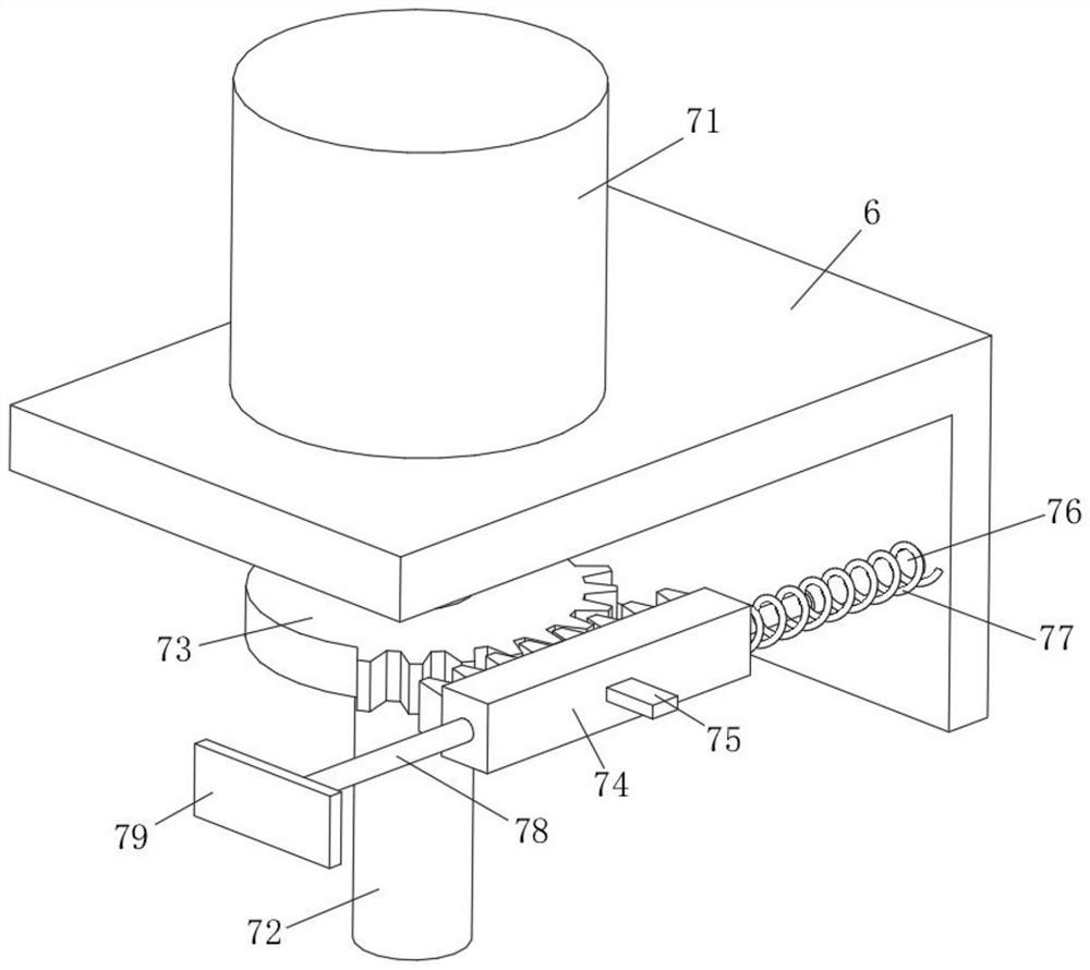
[0036] Such as Figure 1-6 As shown, this embodiment is basically the same as Embodiment 1. Preferably, one end of the spring 77 is fixedly connected to the outer surface of the rack 74 , and the other end of the spring 77 is fixedly connected to the inner wall of the installation box 6 .

[0037] In this embodiment, the spring 77 will be stretched during the movement of the rack 74 , and when the meshing between the first half gear 73 and the rack 74 disappears, the reaction force generated by the spring 77 will drive the push plate 79 back to its original position.

Embodiment 3

[0039] Such as Figure 1-6 As shown, this embodiment is basically the same as Embodiment 1. Preferably, the outer surface of the power shaft 89 is fixed with a convex strip 891 , and the lower end of the power shaft 89 is rotatably connected to the inner bottom surface of the console 1 .

[0040] In this embodiment, the power shaft 89 is rotationally connected to the bottom surface of the console 1 , so that the power shaft 89 can be driven by the second half gear 87 to rotate, avoiding the jamming phenomenon.


PUM


Abstract

The invention discloses a surface detection device for an optical filter product, which comprises an operation table, the upper surface of the operation table is communicated with a protective cylinder, one side surface of the operation table is fixedly provided with an inferior-quality product collection box, the upper surface of the operation table is fixedly provided with a display, the upper surface of the operation table is provided with a bracket, and the bracket is fixedly provided with a support. The opposite faces of the supports are rotationally connected with a conveying belt, flow guide plates are fixedly installed on the opposite faces of the supports, a sliding plate is fixedly installed at one end of each support and arranged above a defective product collecting box, and a trapezoidal outlet is formed in one side face of each support in a penetrating mode. According to the optical filter surface inspection device, through cooperation of all the assemblies, rapid inspection can be achieved when the surfaces of optical filters are inspected, qualified products and unqualified products can be automatically sorted, loss caused by friction between the optical filters can be avoided when the optical filters are collected, and therefore manpower and time are saved, and the production efficiency is improved. And the working efficiency is improved and the cost is saved.

Description

technical field [0001] The invention relates to the technical field of optical filter inspection, in particular to a surface inspection device for optical filter products. Background technique [0002] A filter is an optical device used to select the required radiation band. A common feature of the filter is that no filter can make the image of the celestial body brighter, because all filters will absorb certain wavelengths. Thus making the object darker. [0003] In the process of producing optical filters, the surface of optical filters is mostly inspected manually with naked eyes and light, and when sorting good and defective products, it is also done manually, which is easy to cause inspection errors. Inaccurate results not only waste time, but also reduce work efficiency. When collecting qualified products, most of them are collected manually. During the collection process, it is easy to cause friction between the filters, causing damage to the surface and increasing ...

Claims


Application Information

Patent Timeline
Patent Type & Authority Applications(China)
IPC IPC(8): B07C5/342B07C5/38
CPCB07C5/342B07C5/362B07C5/38
Inventor 李道红
Owner 六安原景智能科技有限公司
Why Eureka
Try Eureka