Multi-air-channel stopper rod

A multi-air channel and stopper technology, which is applied in the direction of casting molten material containers, metal processing equipment, casting equipment, etc., can solve the problems of single argon blowing function and affect the quality of billet, and achieve a balanced and stable flow field of molten steel, ensuring Quality, the effect of preventing slag entrainment

Inactive Publication Date: 2022-03-11
ANHUI UNIVERSITY OF TECHNOLOGY
View PDF2 Cites 1 Cited by
  • Summary
  • Abstract
  • Description
  • Claims
  • Application Information

AI Technical Summary

Problems solved by technology

[0007] The purpose of the present invention is to overcome the problems in the prior art that converging vortexes are easily generated at the nozzle to affect the quality of the slab, and the function of argon blowing is single, and provide a multi-air channel stopper for tundish flow suppression. The present invention can not only realize Inhibition of the confluent vortex generated at the nozzle, and through further development of the existing stopper design, the space utilization rate of the stopper is further increased, and argon blowing can be performed more flexibly

Method used


Image

  • Multi-air-channel stopper rod
  • Multi-air-channel stopper rod
  • Multi-air-channel stopper rod

Examples


Embodiment 1

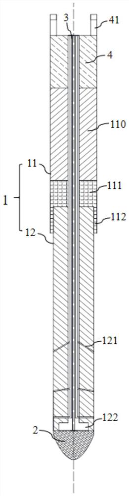
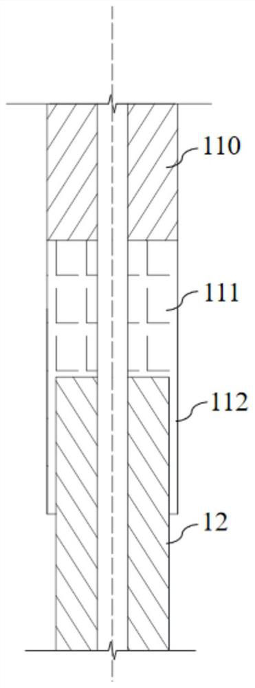
[0038] like figure 1As shown, a multi-airway stopper rod of this embodiment includes a stopper rod body and a stopper rod head 2, the bottom of the stopper rod body is connected to the stopper rod head 2, the stopper rod body includes a stopper rod shell 1 and a rod core 3, and the stopper rod body The rod core 3 is nested in the inner layer of the rod shell 1 . Wherein, the rod core 3 is prepared separately from the stopper shell 1, and the main material of the rod core 3 is high temperature resistant metal. The stopper shell 1 has a plurality of sets of side channels 121 communicating inside and outside, and the core 3 contains an argon gas channel, an important part of the stopper rod. The inner side channel 121 and the bottom argon channel are connected, and each argon channel is made of refractory material, and the argon flow can be controlled in groups from the outside. By setting multiple sets of side channels 121 in the stopper shell 1, the argon flow can be blown ou...

Embodiment 2

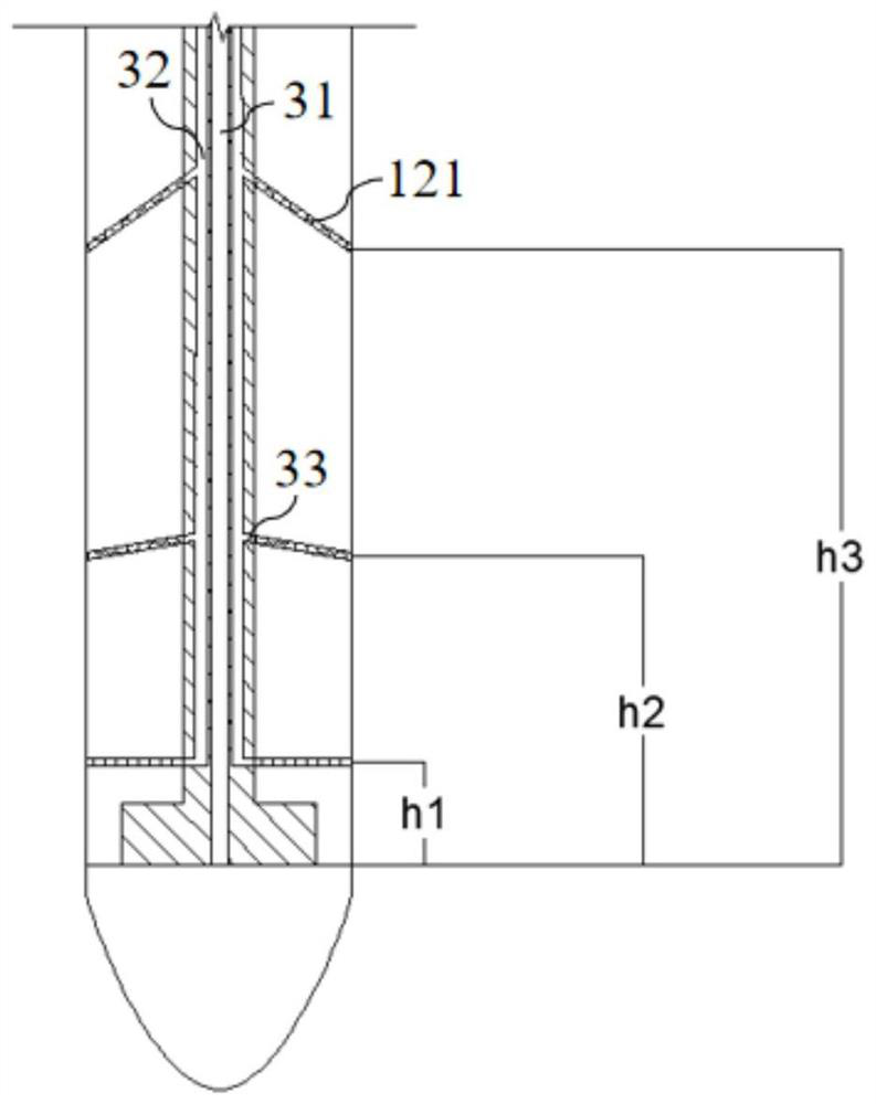
[0047] A kind of multi-airway stopper rod in this embodiment, its structure is basically the same as embodiment 1, and its main difference is: the specific structure of described rod core 3 is different, as Figure 5 As shown, the rod core 3 is designed with a special argon gas channel, which has an axial through pipe as the main channel 31, the upper part is the entrance, and the lower part is connected to the lower rod head. The rod core 3 is provided with six branch channels 32, Each branch channel 32 is provided with a plurality of air guide holes 33 along its axial direction, and an annular transition channel 5 is arranged between the two branch channels 32 distributed symmetrically with the main channel 31, and the branch channels 32 are located at the same height. The air guide holes 33 are connected through the transition channel 5, and the transition channel 5 communicates with the side channel 121, and the connection between the side channel 121 and the transition cha...


PUM


Abstract

The invention discloses a multi-air-channel stopper rod, and relates to the technical field of stopper rods. The multi-air-channel stopper rod comprises a stopper rod body and a stopper rod head, the bottom of the stopper rod body is connected with the stopper rod head, the stopper rod body comprises a stopper rod shell and a rod core, and the rod core is nested in the inner layer of the stopper rod shell; a main channel and a branch channel are arranged in the rod core, and the two ends of the main channel are connected with the argon inlet hole and the stopper rod head respectively. A side channel is arranged in the stopper rod shell, and one end of the branch channel is connected with the argon inlet hole and communicated with the side channel. According to the plug rod, the restraining effect on confluence vortexes generated at the water gap can be achieved, the space utilization rate of the plug rod is further increased by further developing the design of an existing plug rod, and argon blowing can be conducted more flexibly.

Description

technical field [0001] The present invention relates to the technical field of plug rods, and more particularly, to a multi-airway plug rod. Background technique [0002] In the continuous casting process of iron and steel, the tundish has the functions of stabilizing the steel flow and reducing inclusions, and the stopper rod connected to the top of the mold nozzle is to determine whether the molten steel can be stably solidified in the mold to form an ingot, and The quality of the finished product has an important influence. The stopper is an important device to control the flow state of the molten steel entering the mold, and it also plays a role in removing and controlling the inclusions at the nozzle. [0003] The current common stopper rod is basically composed of the stopper rod body, the rod head at the bottom of the stopper rod and the inner argon gas pipeline. The body of the stopper is used to perform its most important function of controlling the flow of the noz...

Claims


Application Information

Patent Timeline
IPC IPC(8): B22D41/18
CPCB22D41/186
Inventor 岳强王秀珍窦为学杨泽曦王子铭
Owner ANHUI UNIVERSITY OF TECHNOLOGY
Why Eureka
Try Eureka