Laser splitting device for cutting optical glass

An optical glass and laser technology, applied in glass cutting devices, glass manufacturing equipment, manufacturing tools, etc., can solve the problems of scrapping optical glass rough embryos, waste of raw materials, and increased cost.

Active Publication Date: 2022-03-11
成都晶华光电科技股份有限公司
View PDF6 Cites 1 Cited by
  • Summary
  • Abstract
  • Description
  • Claims
  • Application Information

AI Technical Summary

Problems solved by technology

Making optical glass into optical components requires cutting and polishing the whole piece of optical glass. In traditional crafts, manual cutting is generally used. The size of the rough optical glass obtained by manual cutting will vary greatly, even after cutting. The mirror surface is worn or broken during the process, so that the rough optical glass blank can not be used, resulting in waste of raw materials and increased cost

Method used


Image

  • Laser splitting device for cutting optical glass
  • Laser splitting device for cutting optical glass
  • Laser splitting device for cutting optical glass

Examples


Embodiment Construction

[0029] The technical solution of the present invention will be further described in detail below in conjunction with the accompanying drawings, but the protection scope of the present invention is not limited to the following description.

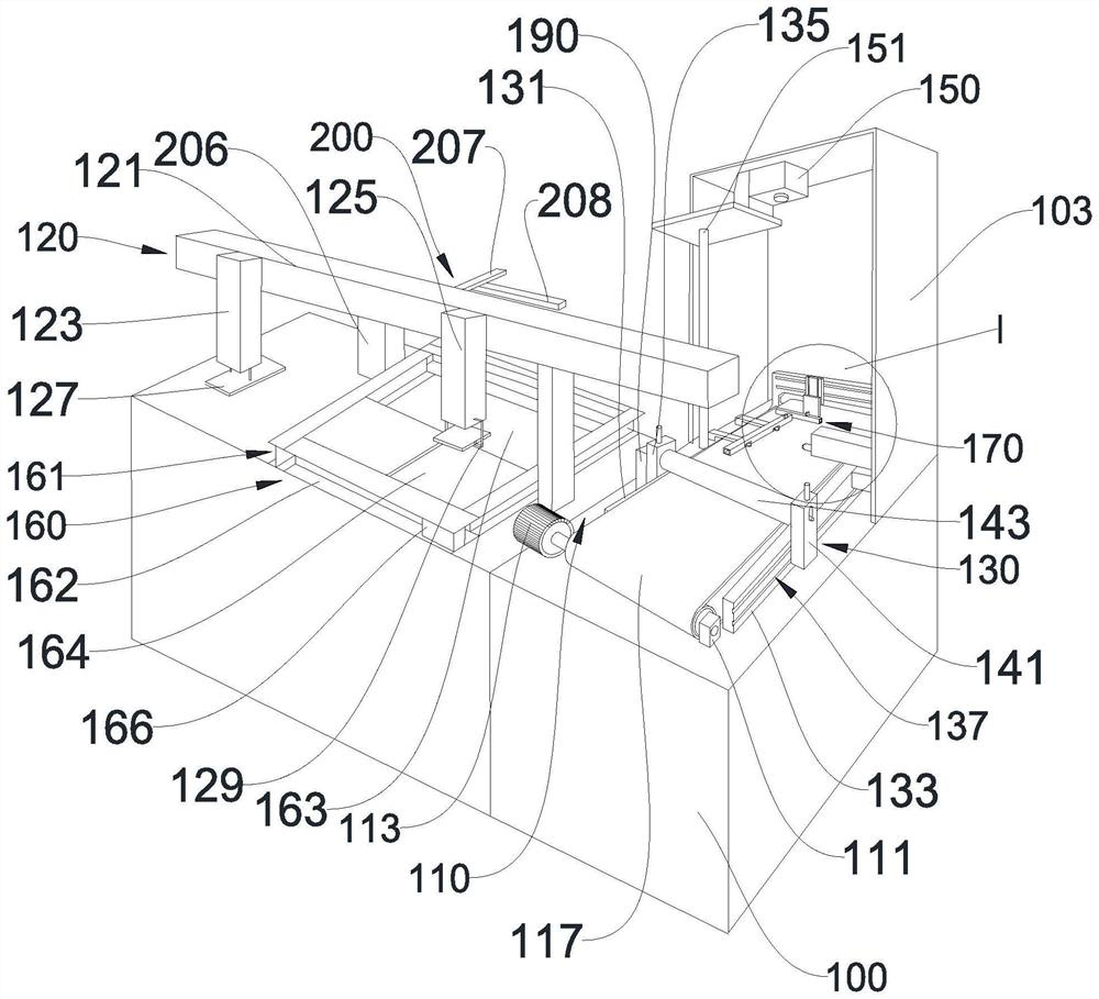
[0030] Please refer to figure 1 As shown, a laser splitting device for cutting optical glass includes a main body 100 and a control system. On the top surface of the main body 100, 120, a first conveying assembly 160, a cutting assembly 200, a second conveying assembly 110, Liquid feeding assembly 130 , secondary cutting heating assembly 150 and positioning assembly 170 . The feeding assembly 120, the first conveying assembly 160, the cutting assembly 200, the second conveying assembly 110, the liquid adding assembly 130, the secondary cutting heating assembly 150 and the positioning assembly 170 are all electrically connected to the control system, and the control system can The program automatically controls the feeding assembly 120 , th...


PUM


Abstract

The invention discloses a laser splitting device for cutting optical glass, which comprises a main machine body and a control system, and is characterized in that a feeding assembly, a first conveying assembly, a cutting assembly, a second conveying assembly, a liquid adding assembly, a secondary cutting heating assembly and a positioning assembly are mounted on the top surface of the main machine body; the feeding assembly is used for conveying optical glass to the first conveying assembly and can convey the optical glass on the first conveying assembly to the second conveying assembly. The cutting assembly is installed above the first conveying assembly, the cutting assembly and the first conveying assembly are arranged in a spaced mode, and the cutting assembly can cut the optical glass on the first conveying assembly; the second conveying assembly is installed between the main machine body and the liquid adding assembly, the top face of the second conveying assembly and the liquid adding assembly are arranged in a spaced mode, and the liquid adding assembly can make contact with the top face of the optical glass. The secondary cutting and heating assembly is located above the second conveying assembly and is separated from the second conveying assembly, and the positioning assembly is located between the second conveying assembly and the secondary cutting and heating assembly.

Description

technical field [0001] The invention relates to the technical field of laser cutting equipment, in particular to a laser splitting device for cutting optical glass. Background technique [0002] Optical glass is a glass that can change the direction of light propagation and change the relative spectral distribution of ultraviolet, visible or infrared light. Optical glass in the narrow sense refers to colorless optical glass; optical glass in the broad sense also includes colored optical glass, laser glass, quartz optical glass, anti-radiation glass, ultraviolet and infrared optical glass, fiber optic glass, acousto-optic glass, magneto-optical glass and photochromic Glass. Optical glass can be used to manufacture lenses, prisms, mirrors and windows in optical instruments. [0003] Optical glass is generally used to manufacture components of optical instruments, so the requirements for making optical glass into optical components are very high. Making optical glass into op...

Claims


Application Information

Patent Timeline
Patent Type & Authority Applications(China)
IPC IPC(8): C03B33/09C03B33/08
CPCC03B33/09C03B33/091C03B33/082
Inventor 汪锐汪闻磊
Owner 成都晶华光电科技股份有限公司
Why Eureka
Try Eureka