
Wire cord fabric detection and calibration device and detection and calibration method

A technology for detecting and calibrating devices and steel cords, which is applied in the direction of material magnetic variables, etc., can solve problems such as different magnetic fields, different original outputs of array magnetic sensitive elements, and difficult detection of image defects, so as to improve accuracy and reliability, and effectively The effect of outstanding information and high calibration accuracy

Pending Publication Date: 2022-03-11
WEIHAI HUALING OPTO ELECTRONICS CO LTD
View PDF9 Cites 1 Cited by
  • Summary
  • Abstract
  • Description
  • Claims
  • Application Information

AI Technical Summary

Problems solved by technology

[0004] In this way of detection device, the discretization between the array magnetic sensitive elements causes the initial state of each magnetic sensitive element to be different, and the initial excitation magnetic field signal of the array magnetic field unit is not the same, resulting in that when there is no steel cord passing through each magnetic sensitive element The magnetic field of each array is different, which eventually leads to different original outputs of each array magnetic sensor when no steel cord passes through, which brings difficulties to subsequent image defect detection
In addition, when the steel cord is continuously conveyed on the detection device, due to environmental changes and magnetization of the steel cord, it will cause continuous impact on the magnetic sensor and the magnetic field unit, resulting in a change in the initial excitation magnetic field, which makes the original output of the magnetic sensor deviate from the initial installation. value, resulting in uneven background magnetic images, which will greatly interfere with the judgment of the subsequent image defect detection unit, so online calibration of the detection device is required; since the detection device installed on the production line and fixed in position is always affected by the steel cord , how to avoid the influence of steel cord and conveniently carry out precise calibration on the detection device, there is no feasible method proposed at present

Method used


Image

  • Wire cord fabric detection and calibration device and detection and calibration method
  • Wire cord fabric detection and calibration device and detection and calibration method
  • Wire cord fabric detection and calibration device and detection and calibration method

Examples


Embodiment 1

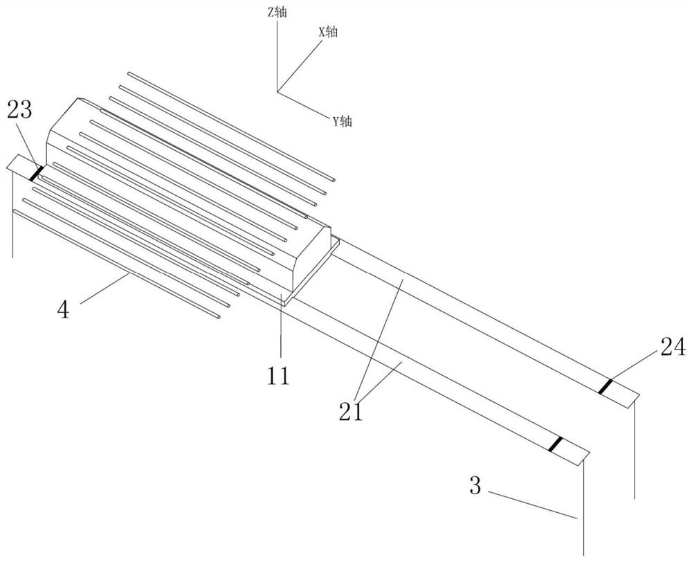
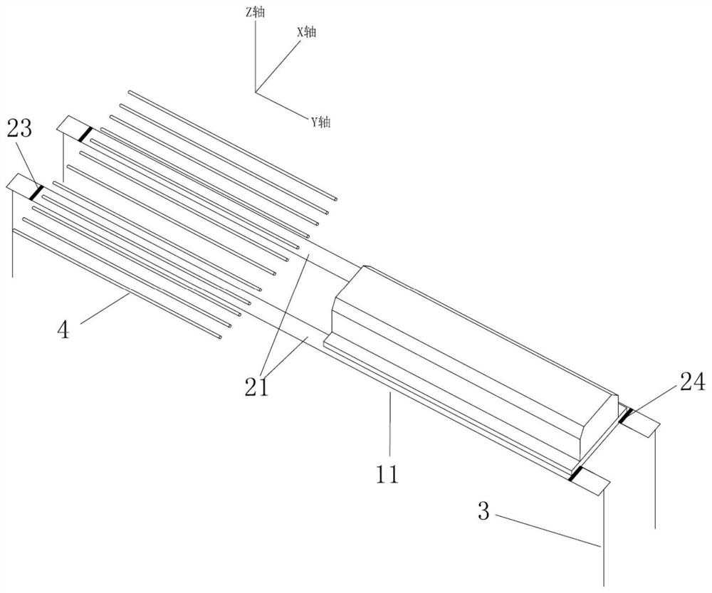
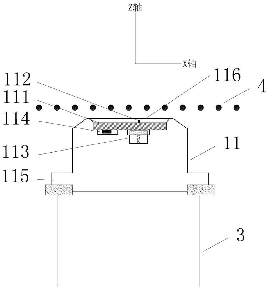
[0087] Such as Figure 4 , Figure 5 As shown, this embodiment provides a steel cord detection and calibration device, including a magnetic sensor module 11 , a first slide rail 21 , a sliding mechanism 6 , a receiving member 5 and a bracket 3 .

[0088] The magnetic sensor module 11 includes a substrate 111 made of PCB material. The substrate 111 is parallel to the width of the steel cord 4. On the surface of the substrate 111 facing the steel cord 4, 216 magnetic sensors are arranged at equal intervals of 0.5 mm along the Y axis. Component 112 forms an effective scanning width of 108 mm and obtains detection signals and calibration signals, both of which are magnetic field signals, specifically, voltage signals reflecting the magnitude of the magnetic field; the surface of the substrate 111 facing away from the side of the steel cord 4 A magnetic unit 113 facing away and a processing unit 114 are provided, the magnetic unit 113 facing away comprises a plurality of magnets a...

Embodiment 2

[0110] Embodiment 2 provides another embodiment of the steel cord detection and calibration device of the present application, Figure 6 It is a schematic diagram of the present embodiment in the detection state, Figure 7 It is a schematic diagram of this embodiment in a calibration state, Figure 8 It is a side view of this embodiment.

[0111] Such as Figure 6 to Figure 8 As shown, the difference between this embodiment and Embodiment 1 is that a first opposing magnetic module 12 and a second slide rail 22 are added, and the first opposing magnetic module 12 is arranged on a side of the steel cord 4 facing away from the magnetic sensor module 11. side, including the first opposing magnetic unit 121 arranged along the Y-axis direction and the first opposing magnetic module frame 122 for inserting and fixing the first opposing magnetic unit 121, the first opposing magnetic module frame 122 Made of non-magnetic and non-magnetized materials; the second slide rail 22 is para...

Embodiment 3

[0114] Embodiment 3 provides another embodiment of the steel cord detection and calibration device of the present application, Figure 9 It is a schematic diagram of the present embodiment in the detection state, Figure 10 Schematic diagram of this implementation in calibration.

[0115] Such as Figure 9 , Figure 10 As shown, the difference between this embodiment and Embodiment 2 is that a second opposing magnetic module 13 is added. In this embodiment, the first opposing magnetic module 12 is positioned at the detection position, and the second opposing magnetic module 13 is positioned At the calibration position, it includes the second opposing magnetic unit arranged along the Y axis and the second opposing magnetic module frame for placing and fixing the second opposing magnetic unit. The second opposing magnetic module frame is made of non-magnetic The first magnetic unit and the second magnetic unit are both of strong magnetic structure and have the same magnetic f...


PUM


Abstract

The invention provides a wirecord fabric detection and calibration device and a detection and calibration method, the wirecord fabric detection and calibration device is used for obtaining a wirecord fabric detection signal and performing calibration through a calibration signal, the wirecord fabric detection and calibration device comprises a detection assembly, a slide rail assembly and a support, the detection assembly comprises a magnetic sensor module, and the magnetic sensor module is used for detecting the wirecord fabric. The magnetic sensor module and the wirecord fabric are not in the same plane, the magnetic sensor module comprises a base plate, a plurality of magnetic sensitive elements, a processing unit and a back magnetic unit, the sliding rail assembly comprises a first sliding rail extending in the preset direction, and the magnetic sensor module is in lap joint with the first sliding rail and can slide along the first sliding rail in a reciprocating mode; the support is used for supporting and fixing the sliding rail assembly. The wirecord fabric detection and calibration device provided by the invention can effectively avoid the influence of magnetized steel cords in the wirecord fabric on the detection device, and is convenient to operate, easy to implement and high in calibration precision.

Description

technical field [0001] The present application relates to the field of industrial non-destructive testing, in particular to a device and method capable of detecting defects in steel cord fabrics and calibrating the detection results. Background technique [0002] Steel cord is an important part of truck tires. It is composed of an outer rubber layer and steel cords wrapped in the rubber layer at equal intervals. As a belt layer of truck tires, it provides important support for strengthening the structural strength and bearing capacity of truck tires. During the manufacturing process of steel cord, due to the influence of production equipment and process flow, the steel wires in the steel cord may have uneven distribution such as bending, dislocation, disconnection, crossing, etc. If the distribution of steel wires in the steel cord cannot be detected in real time, then It will have an adverse effect on the quality of the steel cord, and directly affect the performance and sa...

Claims


Application Information

Patent Timeline
Patent Type & Authority Applications(China)
IPC IPC(8): G01N27/82
CPCG01N27/82
Inventor 戚务昌林永辉姜利张凯
Owner WEIHAI HUALING OPTO ELECTRONICS CO LTD
Learn More