Photovoltaic cable joint connector
A joint connector, cable joint technology, applied in the direction of connection, connecting device components, circuits, etc., can solve the problem of poor joint connection and other problems
- Summary
- Abstract
- Description
- Claims
- Application Information
AI Technical Summary
Problems solved by technology
Method used
Image
Examples
Embodiment 1
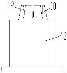
[0030] A photovoltaic cable joint connector in this embodiment includes an outer sleeve (4), a cable joint waterproof sleeve (3), a cable sub-female joint (2) and two cables (1) to be connected. The terminal of the wiring cable (1) is connected through the cable sub-joint (2), and the cable joint waterproof sleeve (3) is sleeved on the cable sub-joint (2) and fixedly connected with the cable sub-joint (2); The cable joint waterproof sleeve (3) is socketed in the outer sleeve (4), and there are two elastic tension discs (5) inside the outer sleeve (4), and the elastic tension discs (5) and the outer sleeve (4) Fixed, the cable joint waterproof sleeve (3) is set between the two elastic clamping discs (5), the two cables to be connected (1) respectively pass through the two elastic clamping discs (5), the elastic clamps The reel (5) is in tight contact with the cable (1) to be connected; the cable to be connected (1) between the cable sub-joint (2) and the elastic clamping reel (...
Embodiment 2
[0041] The difference between this embodiment and Embodiment 1 is that the openings at both ends of the outer sleeve (4) are respectively provided with sleeve plugging heads (7), and the sleeve plugging heads (7) connect with the outer sleeve (4) through bolts. ) to fix and block the end opening of the outer sleeve (4); the two cables to be wired (1) respectively pass through the sleeve plugging head (7) and are fixed with the sleeve plugging head (7) ; The cable to be connected (1) between the sleeve plugging head (7) and the elastic clamping disc (5) is provided with an arc-shaped buffer section two (1-2); the arc-shaped buffer section (1-1 ), arc-shaped buffer section two (1-2) is formed by bending the cable to be connected (1).
[0042] The second arc buffer section (1-2) is set inside the outer sleeve (4), and the outer sleeve ( 4) The tensile deformation range of the cable to be connected (1) is extended to further reduce the tension on the cable sub-joint (2). And due...
PUM
 Abstract
Description
Claims
Application Information
 - R&D
- Intellectual Property
- Life Sciences
- Materials
- Tech Scout
- Unparalleled Data Quality
- Higher Quality Content
- 60% Fewer Hallucinations
Browse by: Latest US Patents, China's latest patents, Technical Efficacy Thesaurus, Application Domain, Technology Topic, Popular Technical Reports.
© 2025 PatSnap. All rights reserved.Legal|Privacy policy|Modern Slavery Act Transparency Statement|Sitemap|About US| Contact US: help@patsnap.com


