Ultra-wide steel box girder total splicing cross slope control method

A control method and steel box girder technology, applied in the direction of manufacturing tools, auxiliary devices, workpiece edges, etc., can solve the problems affecting the overall structural accuracy of steel box girder segments, difficult to effectively guarantee accuracy control, and reducing bridge comfort, etc. The method is simple and feasible, the impact is reduced, and the effect of strong versatility is achieved

Active Publication Date: 2022-03-15
CHINA RAILWAY BAOJI BRIDGE GRP
View PDF9 Cites 2 Cited by
  • Summary
  • Abstract
  • Description
  • Claims
  • Application Information

AI Technical Summary

Problems solved by technology

Ultra-wide steel box girders require higher and higher manufacturing precision. It is difficult to effectively guarantee the precision control of steel box girders manufactured according to the traditional manufacturing process.
Especially after the bridge deck is widened, the number of plate units will increase, the number of butt joints will increase, the length of the transverse weld will increase, and the cumulative effect of the shrinkage of the longitudinal butt weld will have an impact on the control accuracy of the bridge deck’s transverse slope, which will directly affect The overall structural accuracy of the steel box girder section affects the drainage of the bridge deck and reduces the comfort of the bridge in later use

Method used


Image

  • Ultra-wide steel box girder total splicing cross slope control method
  • Ultra-wide steel box girder total splicing cross slope control method
  • Ultra-wide steel box girder total splicing cross slope control method

Examples


Embodiment Construction

[0028] Below in conjunction with specific embodiment and Figure 1 to Figure 6 The present invention will be described in further detail, but the embodiments of the present invention are not limited thereto.

[0029] The invention provides a method for controlling the transverse slope of an ultra-wide steel box girder assembly, which specifically includes the following steps:

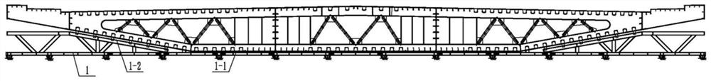
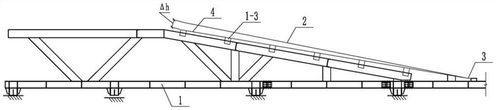
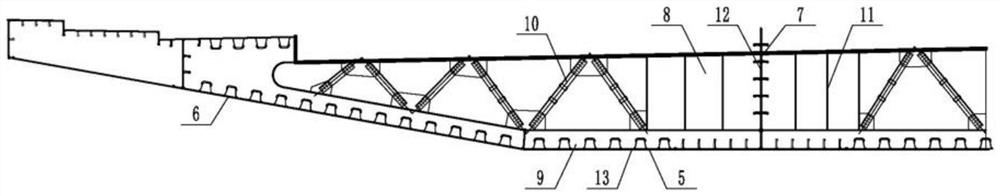
[0030] Step 1: According to the linear requirements of the steel box girder bottom plate, the assembled tire frame 1 is manufactured, and the assembled platform of the assembled tire frame 1 is composed of the horizontal tread 1-1 in the middle and the two ends connected to the horizontal tread 1-1. Symmetrically inclined tread 1-2 constitutes, such as figure 1 shown.

[0031] Step 2: Arranging the tooth plate 1-3 on the horizontal tread 1-1 and the inclined tread 1-2, and the elevation of the tooth plate 1-3 is determined according to the design elevation control line 2 of the steel box girder floor ...


PUM


Abstract

The invention discloses a cross slope control method for ultra-wide steel box girder assembly. The cross slope control method comprises the steps that an assembly jig frame is manufactured; a tooth plate is arranged on the tread; the elevation value of the inclined tread upper tooth plate is corrected according to the design reversible deformation of the steel box girder inclined bottom plate; a flat bottom plate of the steel box girder is placed on the tooth plates on the horizontal tread according to the designed elevation, inclined bottom plates on the two sides of the steel box girder are placed on the corrected tooth plates, and the flat bottom plate and the inclined bottom plates on the two sides are assembled, positioned, welded and fixed; then, the web and the partition plate are assembled, positioned, welded and fixed, vertical butt weld joints of the partition plate are welded firstly, then vertical butt weld joints of the partition plate and the web are welded, and finally transverse structure weld joints of the partition plate and the bottom plate are welded; and finally, the top plate units are assembled, positioned, welded and fixed, butt welding seams of the top plate units are welded firstly, then butt welding seams of the transverse connecting plates on the top plate units are welded, and finally transverse structure welding seams of the transverse connecting plates and the partition plates are welded. According to the method, the structural size precision control level in steel box girder manufacturing is improved, and the cross slope precision of the ultra-wide bridge floor is guaranteed.

Description

technical field [0001] The invention relates to the technical field of bridge engineering, in particular to a method for controlling the transverse slope of super-wide steel box girder assembly. Background technique [0002] With the continuous upgrading of traffic carrying capacity requirements, the road design lanes have gradually developed from the original two-way two-lane lanes to two-way four-lane lanes, and some important urban bridges have appeared steel box girder bridges with the same level of highway and railway. The width is also widened from 30m to 60m. Ultra-wide steel box girders require higher and higher manufacturing precision. It is difficult to effectively guarantee the precision control of steel box girders manufactured according to the traditional manufacturing process. Especially after the bridge deck is widened, the number of plate units will increase, the number of butt joints will increase, the length of the transverse weld will increase, and the cu...

Claims


Application Information

Patent Timeline
Patent Type & Authority Applications(China)
IPC IPC(8): B23K33/00B23K37/00B23K101/28
CPCB23K33/00B23K37/00B23K2101/28Y02A30/60
Inventor 孙磊张晓伟刘治国穆长春饶其文
Owner CHINA RAILWAY BAOJI BRIDGE GRP
Why Eureka
Try Eureka