Optical lens edge grinding device
An optical lens and edging technology, applied in grinding/polishing safety devices, machine tools suitable for grinding the edge of workpieces, grinding machines, etc., can solve the problems of low efficiency, waste recycling, etc., to improve quality, improve efficiency, The effect of reducing labor intensity
- Summary
- Abstract
- Description
- Claims
- Application Information
AI Technical Summary
Problems solved by technology
Method used
Image
Examples
Embodiment 1
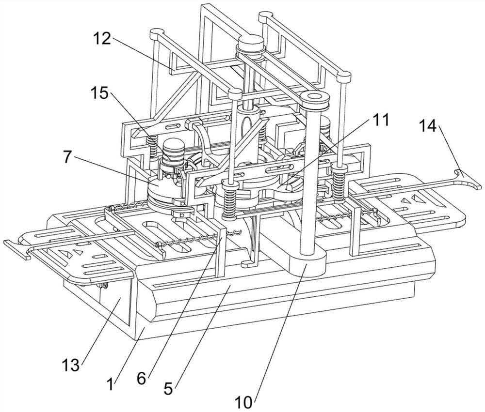
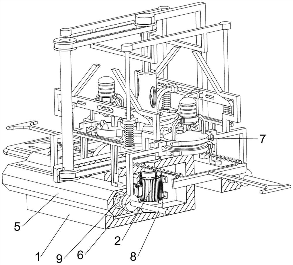
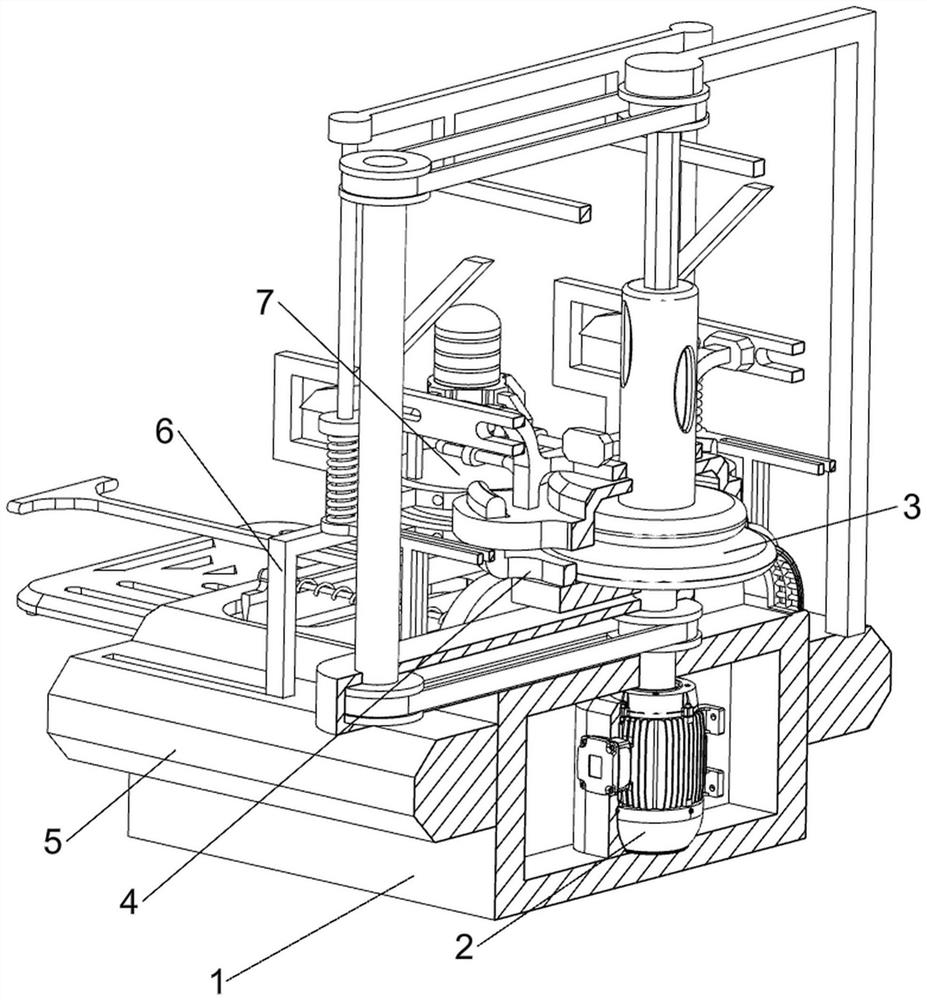
[0040] An optical lens edging device, such as figure 1 , figure 2 , image 3 , Figure 4 , Figure 5 , Image 6 , Figure 7 , Figure 8 , Figure 9 , Figure 10 , Figure 11 , Figure 12 , Figure 14 with Figure 15 As shown, it includes a support block 1, a motor 2, a friction disc 3, a limit ring 4, a limit block 5, a moving rod 6, a grinding stone 7, a guide rod 8, a tension spring 9, a transmission mechanism 10 and a locking mechanism 11. The middle part of the support block 1 is riveted and connected with the motor 2, the output shaft of the motor 2 is connected to the support block 1 in a rotational manner, the output shaft of the motor 2 is fixed with a friction disc 3 through bolts, and the outer side of the friction disc 3 is rotatable Connect the limit ring 4, the limit ring 4 is fixedly connected with the support block 1, the left and right sides of the support block 1 are fixed to the limit block 5 by screws, which is convenient for polishing the optic...
Embodiment 2
[0045] On the basis of Example 1, such as figure 1 , Figure 9 with Figure 10 As shown, a clamping mechanism 12 is also included, and the clamping mechanism 12 includes a first support frame 120, a wedge plate 121, a wedge rod 122, a support seat 123, a limit rod 124, a connecting rod 125 and a first return spring 126, The support ring 110 is provided with a first support frame 120, the left and right sides of the first support frame 120 are all fixedly connected with wedge-shaped plates 121 by bolts, and the tops of the four moving bars 6 are all riveted to be connected with wedge-shaped bars 122, and the wedge-shaped bars 122 and The wedge-shaped plates 121 are snap-fitted, and the tops of the two spacer blocks 5 are fixedly connected with support seats 123 by bolts. Symmetrically arranged, and the limit bar 124 is connected with the wedge-shaped plate 121 slidingly, the upper part of the limit bar 124 is riveted and connected with the connecting rod 125, and the first re...
Embodiment 3
[0048] On the basis of Example 2, such as figure 1 , Figure 11 , Figure 12 , Figure 13 with Figure 14 As shown, a collection mechanism 13 is also included, and the collection mechanism 13 includes a protective plate 130, a second clamping block 131, a limit plate 132 and a collection frame 133, and the front and rear sides of the support block 1 are hingedly connected with two protective plates 130, And the protective plates 130 are snap-fitted with the support block 1, the tops of the four protective plates 130 are fixedly connected with the second block 131 by screws, the front and rear sides of the support block 1 are connected with the limit plate 132, the limit plate 132 and The second clamping block 131 is slidably connected, and the front and rear sides of the support block 1 are slidably connected to the collection frame 133 .
[0049] In the process of polishing the optical lens, the waste debris from the polishing of the optical lens falls into the collection...
PUM
 Abstract
Description
Claims
Application Information
 - R&D
- Intellectual Property
- Life Sciences
- Materials
- Tech Scout
- Unparalleled Data Quality
- Higher Quality Content
- 60% Fewer Hallucinations
Browse by: Latest US Patents, China's latest patents, Technical Efficacy Thesaurus, Application Domain, Technology Topic, Popular Technical Reports.
© 2025 PatSnap. All rights reserved.Legal|Privacy policy|Modern Slavery Act Transparency Statement|Sitemap|About US| Contact US: help@patsnap.com


