Flexible gabion mesh weaving equipment and working method thereof
A kind of character and mesh technology, applied in the direction of braided fabrics, twisted lace looms, textiles and papermaking, etc., can solve the problems of unstable direction, wrinkles, easy deformation of the wire mesh structure, etc.
- Summary
- Abstract
- Description
- Claims
- Application Information
AI Technical Summary
Problems solved by technology
Method used
Image
Examples
no. 1 example
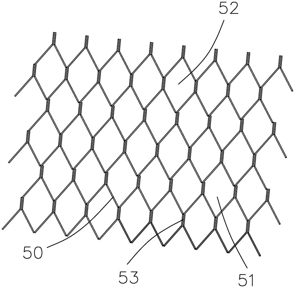
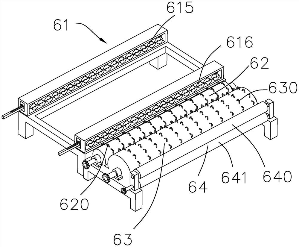
[0045] Such as Figure 1 to Figure 17As shown, the present embodiment provides a flexible gabion weaving equipment, which includes a wire feeding device 60, a stranding assembly 61, a traction roller 62, a heating roller 63 and an extrusion roller group 64 arranged in sequence, and the wire feeding device 60 Supply the wire 1, the wire 1 is a flexible plastic wire, the stranding assembly 61 weaves the passing wire 1 to form the wire mesh structure 50 of the continuous rhombus unit 51, the traction roller 62 drives the mesh 52 of the wire mesh structure 50 to pull and move, heat The roll 63 is located between the traction roll 62 and the extruding roll set 64, the extruding roll set 64 has an upper rotating pinch roll 640 and a lower rotating pinch roll 641, and the wire mesh structure 50 is rotated from the upper rotating pinch roll 640 and the lower rotating pinch roll. The middle of the holding roller 641 passes through.
[0046] The threads used for the mesh structure 50 a...
no. 2 example
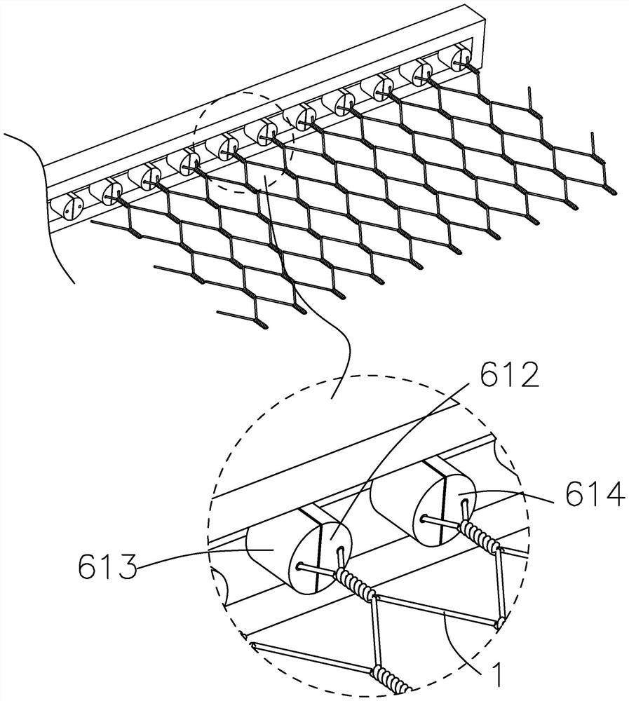
[0052] The stranding assembly 61 of this embodiment has an upper row of rollers 610 and a lower row of rollers 611, the upper row of rollers has a plurality of upper semicircle winding blocks 612 arranged at intervals, and the lower row of rollers 611 has a plurality of lower rollers arranged at intervals. The semicircle winding block 613, and the upper row of rollers 610 and the lower row of rollers 611 can move mutually, that is, the misplacement movement occurs, so that the upper semicircle winding block 612 of the upper row of rollers 610 can be selectively connected with the lower row of rollers 611 The two adjacent lower semicircle winding blocks 613 cooperate to form a complete circular structure 614; the twisting assembly 61 is two groups of structures, including the twisting assembly 615 arranged on the front side and the twisted assembly arranged on the rear side respectively. Component 616.
[0053] Such as figure 2 , image 3 , Figure 4 Shown is an existing pr...
no. 3 example
[0056] Such as Figure 5 to Figure 16 As shown, the present invention provides a wire feeding device for screen production, which includes a rear wire feeding unit 10, a front wire feeding unit 20 and a guide unit 30;
[0057] Such as Figure 12 As shown, the rear wire feeding unit 10 has a rear wire feeding roller 11, and the rear wire feeding roller 11 has a first wire 1;
[0058] Such as Figure 8 , Figure 13 , Figure 14 As shown, the front row wire feeding unit 20 has a rotary driving structure 21 and a front row wire feeding roller 22, the rotary driving structure 21 is connected with the front row wire feeding roller 22 to drive rotation, and the annular interior of the front row wire feeding roller 22 is arranged with a second The wire 2 has an engaging groove 23 on the annular outer portion of the front wire feeding roller 22;
[0059] Such as Figure 6 , Figure 10 , Figure 11 As shown, the guide unit 30 is arranged between the rear wire feeding unit 10 and...
PUM
 Abstract
Description
Claims
Application Information
 - R&D
- Intellectual Property
- Life Sciences
- Materials
- Tech Scout
- Unparalleled Data Quality
- Higher Quality Content
- 60% Fewer Hallucinations
Browse by: Latest US Patents, China's latest patents, Technical Efficacy Thesaurus, Application Domain, Technology Topic, Popular Technical Reports.
© 2025 PatSnap. All rights reserved.Legal|Privacy policy|Modern Slavery Act Transparency Statement|Sitemap|About US| Contact US: help@patsnap.com


