Bilateral bidirectional slip form milling device

A sliding form and milling technology, which is applied in the field of double-sided two-way sliding form milling and planing devices, can solve the problems of inconvenient turning of the mold traction equipment of the sliding form machine, single function of the sliding form machine, and inconvenient supply of concrete, etc., to achieve improved groove milling The effect of planing construction efficiency, avoiding the inconvenience of turning around, and reducing construction costs

Pending Publication Date: 2022-03-15
徐建
View PDF0 Cites 3 Cited by
  • Summary
  • Abstract
  • Description
  • Claims
  • Application Information

AI Technical Summary

Problems solved by technology

[0007] The purpose of the present invention is to provide a double-sided two-way sliding form milling device, which solves the problem of the single function of the sliding form machine in the prior art on the one hand, and also solves the inconvenience of turning around the mold pulling equipment of the sliding form machine and the concrete The problem of inconvenient supply

Method used


Image

  • Bilateral bidirectional slip form milling device
  • Bilateral bidirectional slip form milling device
  • Bilateral bidirectional slip form milling device

Examples


Embodiment 1

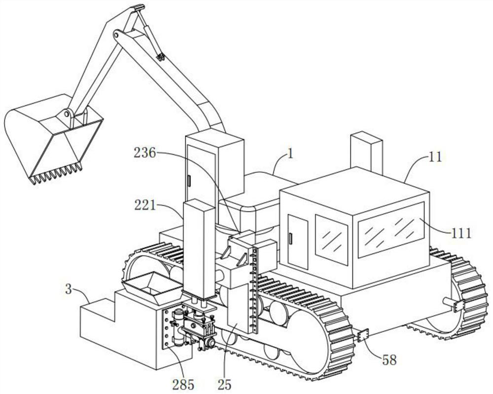
[0044] Such as Figure 1-Figure 10 As shown, a double-sided two-way sliding form milling device includes a traction device 1, a tractor and a slipform machine mold 3 or a milling machine 4 installed on the tractor. The upper end of the traction device 1 is provided with a slipform milling Operating room 11, slipform milling operating room 11 is located at the cab rear of traction equipment 1, it should be noted that traction equipment 1 of the present invention can be excavator, automobile or other self-propelled vehicle equipment, in this embodiment Adopt excavator, do not influence protection scope of the present invention. Specifically, transparent windows 111 are provided on the four side walls of the slipform milling operation room 11 in this embodiment, so that the operator can easily know the working status of the slipform machine mold 3 or the milling machine 4 for easy operation.

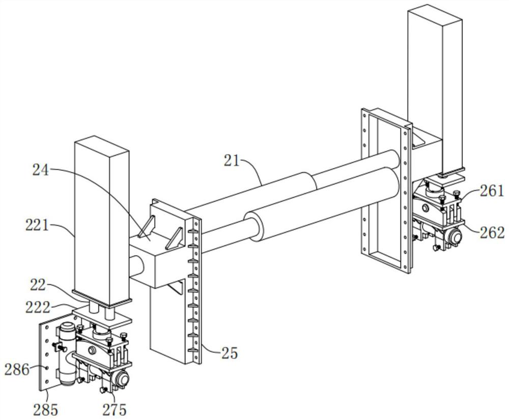
[0045] The tractor includes a horizontal hydraulic cylinder 21 for adjusting the dista...

Embodiment 2

[0056] As a further preferred implementation mode of the present invention, the same features of this embodiment and embodiment 1 will not be repeated, and the different features are:

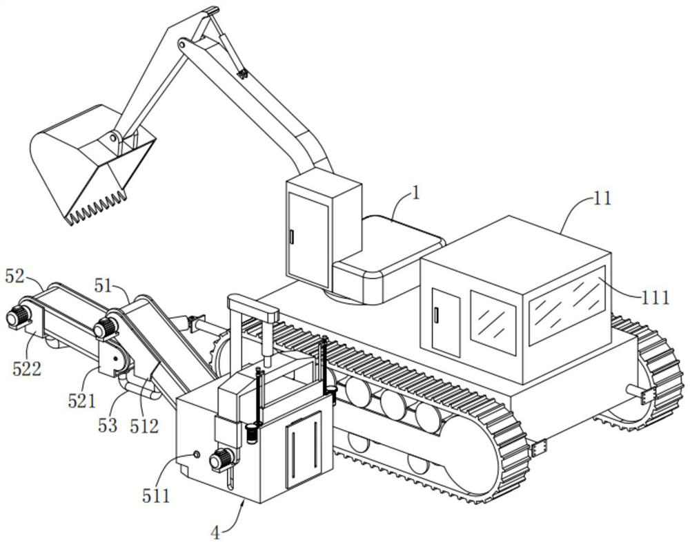
[0057] refer to figure 2 , Figure 8 , Figure 9 , the slipform milling device in this embodiment also includes an aggregate conveying device, the aggregate conveying device includes a first conveyor 51 and a second conveyor 52, and the driving motors of the first conveyor 51 and the second conveyor 52 are both Connected with the control module, the first conveyor 51 is arranged obliquely, its feeding end extends into the inside of the housing 41 of the milling machine 4 and is connected with the housing 41 through the first connecting shaft 511, and the feeding end of the second conveyor 52 Be positioned at the below of the discharge end of the first conveyor 51; The discharge end of the first conveyor 51 is provided with the first support 512, the loading end of the second conveyor 52 is p...

Embodiment 3

[0059] As a further preferred embodiment of the present invention, the same features of this embodiment and embodiment 2 will not be repeated, and the different features are:

[0060] refer to Figure 8-Figure 9 In this embodiment, a height-adjustable retaining plate 44 is vertically arranged on the inner side of the housing 41 away from the end of the first conveyor 51 , and the width of the retaining plate 44 is slightly smaller than the length of the milling rotor 42 .

[0061] Specifically, the upper end of the soil retaining plate 44 in this embodiment penetrates the top of the housing 41 and is slidably fitted with it. Both sides are provided with a servo motor 442 for driving the screw 441 to rotate around the axis. The servo motor 442 is connected to the control module. The screw rod is provided with a sleeve 443 threaded with it, and a transverse connecting rod 444 is provided on the outside of the sleeve 443 , the transverse connecting rod 444 is fixed to the upper ...


PUM


Abstract

The invention discloses a bilateral bidirectional slip-form milling device which comprises traction equipment, a tractor and a slip-form machine mold or a milling machine mounted on the tractor, a slip-form milling operation room is arranged at the upper end of the traction equipment, and the slip-form milling operation room is located behind a cab of the traction equipment; the tractor comprises a transverse hydraulic cylinder used for adjusting the distance between the slip form machine mold or the milling machine and the traction equipment, a vertical hydraulic cylinder used for adjusting the ground clearance of the slip form machine mold or the milling machine, and a direction angle adjusting mechanism used for adjusting the front-back inclination angle, the left-right inclination angle and the orientation of the slip form machine mold or the milling machine; the slip form machine mold or the milling machine is mounted on one side of the direction angle adjusting mechanism; the milling machine comprises a shell with an opening in the lower portion and a height-adjustable milling rotor installed on the inner side of the shell, and a milling motor used for driving the milling rotor to rotate is arranged on the outer side of the shell. The double-side bidirectional sliding formwork or milling construction operation can be achieved, the functions are diversified, and the construction efficiency is higher.

Description

technical field [0001] The invention relates to the technical field of road construction equipment, in particular to a double-sided bidirectional sliding form milling device. Background technique [0002] Sliding form engineering technology is a kind of construction with high degree of mechanization, fast construction speed, less site occupation, strong structural integrity, good seismic performance, safe operation guarantee, and remarkable comprehensive environmental and economic benefits in the construction of cast-in-place concrete structures in my country. technique, often referred to simply as "slip mode". [0003] The most prominent feature of the sliding formwork technology is that the fixed formwork is canceled and the fixed dead formwork is changed into a sliding movable steel formwork, so that there is no need to prepare a large number of fixed formwork erection technologies, and only use pull wires, lasers, sonar, ultrasonic waves, etc. as structural elevations. ,...

Claims


Application Information

Patent Timeline
Patent Type & Authority Applications(China)
IPC IPC(8): E01C19/50E01C23/088
CPCE01C19/508E01C23/088
Inventor 徐建
Owner 徐建
Why Eureka
Try Eureka