Hydraulic jet drilling pipe column and hydraulic jet drilling method

A technology of hydraulic jetting and drilling pipes, which is applied to drilling equipment and methods, drilling with liquid/gas jets, drilling equipment, etc., and can solve the problems of multiple operating links, difficulty in drilling pipe strings, and high operating costs

Active Publication Date: 2022-03-15
PETROCHINA CO LTD
View PDF7 Cites 2 Cited by
  • Summary
  • Abstract
  • Description
  • Claims
  • Application Information

AI Technical Summary

Problems solved by technology

[0005] The purpose of the present invention is to provide a hydraulic jet drilling string and a hydraulic jet drilling method, so as to alleviate the technical problems of the hydraulic jet drilling operation, such as the difficulty in running the drilling string, many operating links and high operating costs.

Method used


Image

  • Hydraulic jet drilling pipe column and hydraulic jet drilling method
  • Hydraulic jet drilling pipe column and hydraulic jet drilling method
  • Hydraulic jet drilling pipe column and hydraulic jet drilling method

Examples


Embodiment 1

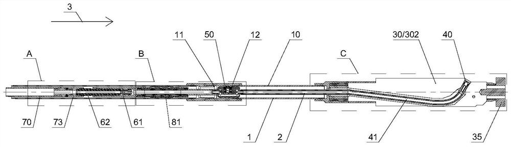
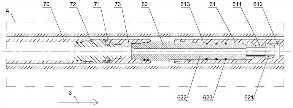
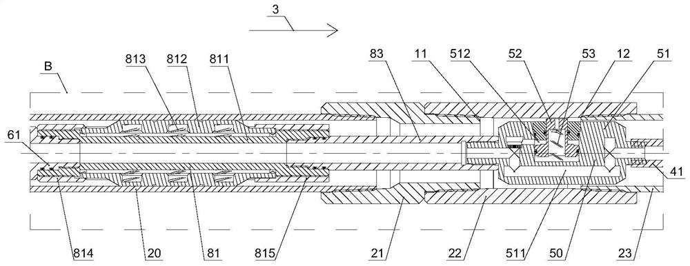
[0085] The invention provides a hydraulic jet drilling string, such as Figure 1 ~ Figure 4 As shown, the hydraulic jet drilling string includes: an outer pipe string 1 and an inner pipe string 2 arranged in the outer pipe string 1; the outer pipe string 1 includes: an outer pipe body 10 and a guide 30, and the outer pipe body 10 The inner wall is provided with a first step 11 and a second step 12 distributed along the direction 3 from bottom to top; the guide 30 is connected to the lower end of the outer tube body 10, and is provided with a hose traveling channel 301; the inner tube column includes: a nozzle 40 , the injection hose 41, the action conversion mechanism 50, the first butt joint 61, the second butt joint 62, and the inner tubing string running into the oil pipe 70; the injection hose 41 is located in the hose travel passage 301, and can move in the hose travel passage 301, The nozzle 40 is connected to the lower end of the injection hose 41; the action conversion...

Embodiment 2

[0113] The present invention provides a hydraulic jet drilling method, using the above hydraulic jet drilling string, such as Figure 19 As shown, the hydraulic jet drilling method includes: Step S10, installing the nozzle 40, the jetting rubber hose 41, the action conversion mechanism 50 and the first butt joint 61 in the outer pipe string 1; Step S20, lowering the outer pipe string 1 into the to the designated formation; step S30, run in the second butt joint pipe 62 and the inner pipe string into the oil pipe 70 in sequence, so that the second butt joint pipe 62 is plugged and communicated with the first butt pipe 61; step S40, pass into the inner pipe string Mortar liquid, the mortar liquid entering the conversion pipe body 51 makes the positioning and limiting pin shaft 52 shrink inwardly, and at the same time, the mortar liquid is sprayed outward through the nozzle 40 to open a window on the casing; step S50, push the inner pipe string down to make the nozzle 40 enters t...


PUM


Abstract

The invention provides a hydraulic jet drilling pipe column and a hydraulic jet drilling method. The hydraulic jet drilling pipe column comprises an outer pipe column body and an inner pipe column body arranged in the outer pipe column body. The outer pipe column comprises an outer pipe body and a guider, and a first step and a second step which are distributed from bottom to top are arranged on the inner wall of the outer pipe body; the inner pipe column comprises a nozzle, a spraying rubber pipe, an action switching mechanism, a first butt joint pipe, a second butt joint pipe and an inner pipe column tripping-in oil pipe. The action switching mechanism comprises a pin shaft spring, a switching pipe body connected to the upper end of the spraying rubber pipe and a positioning limiting pin shaft installed on the switching pipe body. The first butt-joint pipe is connected to the upper end of the conversion pipe body, the second butt-joint pipe can be connected with the first butt-joint pipe in an inserted mode and communicated with the first butt-joint pipe, and the inner pipe column tripping-in oil pipe is connected to the upper end of the second butt-joint pipe and fixedly connected through a shear pin. By means of the hydraulic jet drilling device, the technical problems that in the hydraulic jet drilling operation, the drilling pipe column tripping-in difficulty is large, the number of operation links is large, and the operation cost is high are solved.

Description

technical field [0001] The invention relates to the field of oil recovery in oil fields, in particular to a hydraulic jet drilling string and a hydraulic jet drilling method. Background technique [0002] Hydrojet drilling technology is a production stimulation process. First, a window is opened in the casing of a specified layer in the downhole, and then the drilling string forms long-distance radial holes in the formation through the window, which can directly and effectively communicate with the fractures at the far end of the reservoir. Or the wellbore near the wellbore can be unplugged, the permeability of the production interval can be improved, the remaining oil between the wells can be produced, and the production and efficiency can be increased. Hydrojet drilling technology can be applied to low-permeability oil field development, such as geological exploration, oil well stimulation, improving steam injection and water injection effects, etc. [0003] Hydrojet dril...

Claims


Application Information

Patent Timeline
IPC IPC(8): E21B7/18E21B7/20E21B29/06
CPCE21B7/18E21B7/20E21B29/06Y02P70/10
Inventor 孔凡楠于广刚胡胜勇张曦宇王文钢张洪志苗春旭张升峰温海波杨雨潇韩菁华高依然贾纯真卢潇赵云峰
Owner PETROCHINA CO LTD
Why Eureka
Try Eureka