Ultrasonic nondestructive testing device for pipeline defects

A non-destructive testing and ultrasonic technology, applied in measuring devices, using sonic/ultrasonic/infrasonic waves to analyze solids, and using sonic/ultrasonic/infrasonic waves for material analysis, etc. Reduce consumption costs, overcome strong liquidity, and ensure the effect of accuracy

Pending Publication Date: 2022-03-15
蚌埠市特种设备监督检验中心
View PDF1 Cites 2 Cited by
  • Summary
  • Abstract
  • Description
  • Claims
  • Application Information

AI Technical Summary

Problems solved by technology

[0003] However, the above-mentioned ultrasonic flaw detection method, the manufacturing method of the welded steel pipe and the ultrasonic flaw detection device still have obvious defects in the use process: 1. The above-mentioned device controls the rotation and forward and backward movement of the pipeline through the driving mechanism, while the ultrasonic detection device is fixed. This detection method requires a large mechanism to hoist and support the pipeline at both ends of the pipeline. It takes a lot of time during the hoisting and testing process, and the pipeline needs to be moved, which is not conducive to rapid testing. 2. When doing ultrasonic flaw detection, the air between the ultrasonic probe and the surface of the workpiece to be tested will prevent the ultrasonic wave from passing into the workpiece. In order to make the ultrasonic wave penetrate into the workpiece effectively, ensure that there is enough sound Strong transmittance, in order to achieve the purpose of detection, a liquid conductive medium is needed to connect the probe and the workpiece to be tested. This medium is the couplant, that is, the ultrasonic couplant. The above-mentioned device cannot automatically apply the couplant during the detection process and requires manual labor. Coating reduces the detection efficiency. In addition, the couplant in the prior art is usually one of engine oil, transformer oil, grease, glycerin, water glass or industrial glue, and chemical paste. The above materials have the ability to lubricate, flow The characteristics of poor performance and slow air-drying are widely used in the field of ultrasonic flaw detection, and liquid water in life also meets the characteristics of couplant and is suitable as a couplant medium, but its strong fluidity and easy drying characteristics make it impossible to use it on non-planar components. Compared with the above-mentioned couplants, water is used in flaw detection, the cost is greatly reduced, and the difficulty of later cleaning is low; 3. Because water will cause smear loss after contact with components, and water loss will cause air bubbles in the detection area, which will lead to flaw detection The situation that the work cannot be carried out occurs, and this problem is effectively solved in the prior art

Method used


Image

  • Ultrasonic nondestructive testing device for pipeline defects
  • Ultrasonic nondestructive testing device for pipeline defects
  • Ultrasonic nondestructive testing device for pipeline defects

Examples


Embodiment 1

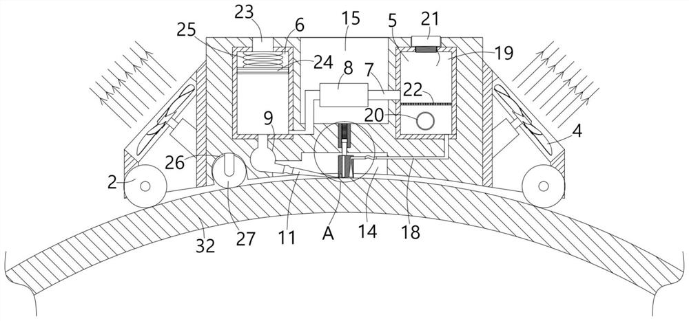
[0028] An ultrasonic non-destructive testing device for pipeline defects, comprising a testing frame 1 and four Mecanum wheels 2 controlled by independent motors installed at the bottom of the testing frame 1, and an ultrasonic non-destructive testing box 3 is fixedly installed in the middle of the testing frame 1 , a number of reverse thrust fan blades 4 are fixedly installed on the side of the ultrasonic nondestructive testing box 3;

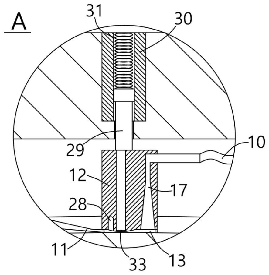
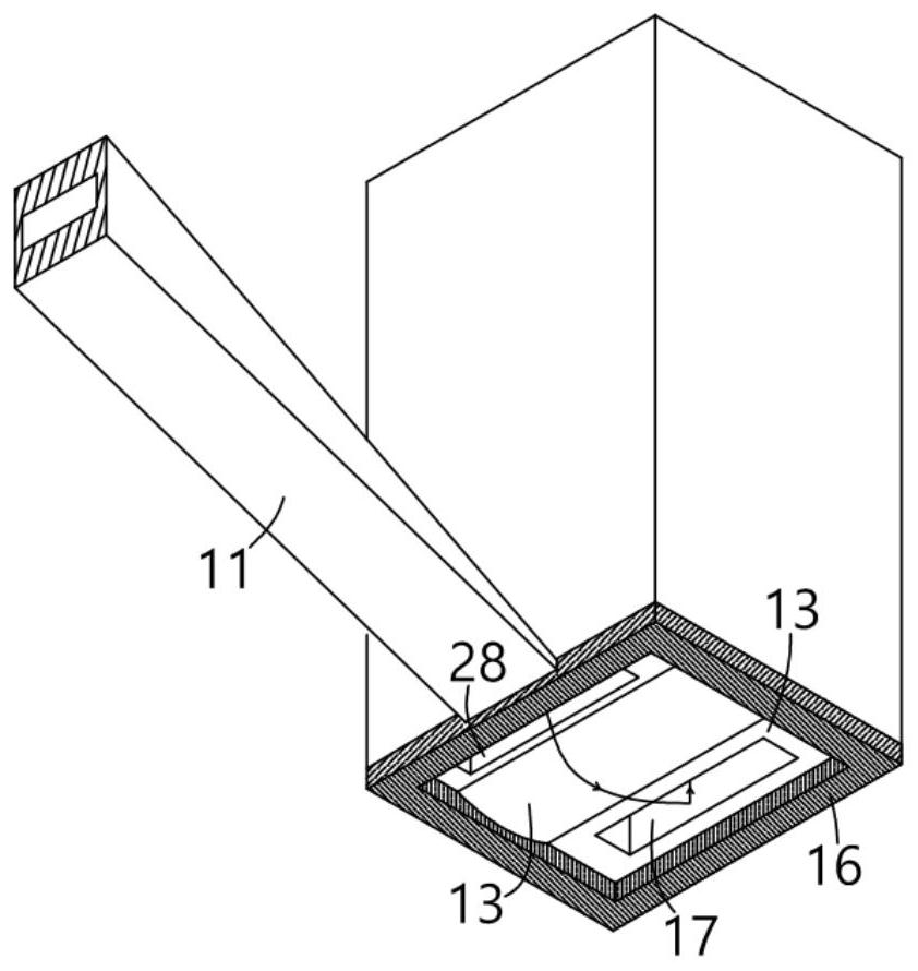
[0029] The ultrasonic non-destructive testing box 3 is equipped with a filter cabin 5 and a liquid supply cabin 6. The filter cabin 5 and the liquid supply cabin 6 are connected through a transition pipe 7. The pipe 9 communicates with the driven liquid supply pipe 11 through the flexible pipe 10, the liquid outlet of the driven liquid supply pipe 11 is located in the detection area 13 provided at the bottom of the detection probe 12, and the detection probe 12 is arranged in the ultrasonic nondestructive testing box 3 In the detection cabin 1...

Embodiment 2

[0032] In this embodiment, a water injection port 19 and a filter port 20 are respectively provided on one side of the ultrasonic non-destructive testing box 3 where the filter cabin 5 is located. The water port 19 replenishes water into the filter cabin 5, and the circulating impurities in the filter cabin 5 are cleaned through the filter port 20.

Embodiment 3

[0034] In this embodiment, a grid filter plate 22 is fixedly installed in the filter cabin 5, the water injection port 19 and the filter port 20 are respectively located on the upper and lower sides of the grid filter plate 22, and the transition pipe 7 is arranged in the filter cabin 5 near the water injection port 19. On one side, impurities are filtered through the grid filter plate 22, so as to ensure that the liquid entering the transition pipe 7 is kept clean, thereby ensuring the accuracy of flaw detection.


PUM


Abstract

The invention provides an ultrasonic nondestructive detection device for pipeline defects, which comprises a detection frame and four Mecanum wheels mounted at the bottom of the detection frame and controlled by an independent motor, an ultrasonic nondestructive detection box is fixedly mounted in the middle of the detection frame, and a filter cabin is communicated with a liquid supply cabin through a transition pipeline. A circulating pump is arranged on the transition pipeline, a liquid return channel is formed in the detection probe on the side, away from the driven liquid supply pipe, of the arc-shaped ultrasonic detection area, and the liquid return channel is communicated with the filtering cabin through a flexible pipe and a liquid return pipeline; the detection frame is firmly limited on the surface of the pipeline by applying strong airflow thrust to one side far away from the pipeline through the reverse thrust fan blades, and liquid water is used as a coupling medium to replace a coupling agent in the prior art, so that the defects that the liquid water is easy to air in a long-term detection process due to high flowability on the surface of the arc-shaped pipeline are overcome; bubbles are effectively eliminated in the detection process, and the accuracy of ultrasonic bubble detection is ensured.

Description

technical field [0001] The invention relates to the technical field of ultrasonic flaw detectors, in particular to an ultrasonic nondestructive testing device for pipeline defects. Background technique [0002] In the prior art, the publication number is "CN101467035B", an ultrasonic flaw detection method, a welded steel pipe manufacturing method and an ultrasonic flaw detection device, including disposing an angled probe on the outer surface of the welded steel pipe, so that the transverse wave ultrasonic beam in the welded steel pipe The propagation direction of the weld bead is approximately perpendicular to the length direction of the weld bead, and the end stop of the weld bead on the inner surface of the welded steel pipe with the shortest distance from the bevel probe constitutes an angle of more than 40 degrees and less than 55 degrees. Transverse wave ultrasonic beam propagation at the refraction angle. After configuration, the welded steel pipe is inspected by an a...

Claims


Application Information

Patent Timeline
Patent Type & Authority Applications(China)
IPC IPC(8): G01N29/265G01N29/04G01N29/28G01N29/32
CPCG01N29/265G01N29/04G01N29/28G01N29/32G01N2291/023
Inventor 王念王大伟汪涛宋家启刘杨杨
Owner 蚌埠市特种设备监督检验中心
Why Eureka
Try Eureka