Supercharge Your Innovation With Domain-Expert AI Agents!

Band-gap reference voltage source circuit, integrated circuit and electronic equipment

A reference voltage source, reference source technology, applied in the direction of adjusting electrical variables, control/regulating systems, instruments, etc., can solve the problem of high power consumption, low power supply suppression, and reduced use of bandgap reference voltage source circuits. performance issues

Pending Publication Date: 2022-03-15
HANGZHOU HIKMICRO SENSING TECH CO LTD
View PDF5 Cites 0 Cited by
  • Summary
  • Abstract
  • Description
  • Claims
  • Application Information

AI Technical Summary

Problems solved by technology

[0003] The inventors have found that there are at least the following technical problems in the prior art: the power supply rejection of the bandgap reference voltage source circuit is relatively low, and the fluctuation of the power supply voltage easily affects the output voltage of the bandgap reference voltage source circuit, which reduces the performance of the bandgap reference voltage source circuit. The reliability of the circuit, and the power consumption of the bandgap reference voltage source circuit is relatively large, which reduces the performance of the bandgap reference voltage source circuit

Method used


Image

  • Band-gap reference voltage source circuit, integrated circuit and electronic equipment
  • Band-gap reference voltage source circuit, integrated circuit and electronic equipment
  • Band-gap reference voltage source circuit, integrated circuit and electronic equipment

Examples


Embodiment Construction

[0038] Embodiments of the present invention will be described in detail below in conjunction with the accompanying drawings.

[0039] In describing the present invention, it is to be understood that the terms "center", "upper", "lower", "front", "rear", "left", "right", "vertical", "horizontal", The orientations or positional relationships indicated by "top", "bottom", "inner", "outer", etc. are based on the orientations or positional relationships shown in the drawings, and are only for the convenience of describing the present invention and simplifying the description, rather than indicating or implying References to devices or elements must have a particular orientation, be constructed, and operate in a particular orientation and therefore should not be construed as limiting the invention.

[0040] The terms "first" and "second" are used for descriptive purposes only, and cannot be understood as indicating or implying relative importance or implicitly specifying the quantit...


PUM


Abstract

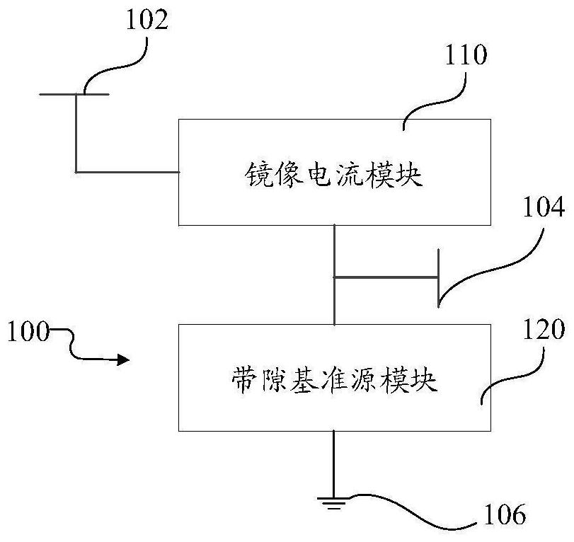
The invention discloses a band-gap reference voltage source circuit, an integrated circuit and electronic equipment, relates to the technical field of analog circuits, and aims to solve the problems of relatively low power supply rejection and relatively high power consumption of a band-gap reference voltage source circuit in the prior art. The coupling element couples an alternating current signal from the circuit input end to the mirror current module. And the mirror current module is started under the control of an electric signal from the band-gap reference source module, and inputs a direct-current electric signal to the band-gap reference source module according to an electric signal from the circuit input end, an electric signal from the band-gap reference source module and an alternating-current electric signal from the coupling element. And the alternating current electric signal from the coupling element is used for compensating the electric signal from the band-gap reference source module. And the band-gap reference source module enables the output voltage of the circuit output end to be within a preset reference voltage range according to the direct current signal from the mirror current module. The band-gap reference voltage source circuit provided by the invention is used for outputting voltage within a preset reference voltage range.

Description

technical field [0001] The invention relates to the technical field of analog circuits, in particular to a bandgap reference voltage source circuit, an integrated circuit and an electronic device. Background technique [0002] In the prior art, an analog integrated circuit usually includes a bandgap reference voltage source circuit, and the output voltage of the bandgap reference voltage source circuit remains approximately stable as the temperature changes. [0003] The inventors have found that there are at least the following technical problems in the prior art: the power supply rejection of the bandgap reference voltage source circuit is relatively low, and the fluctuation of the power supply voltage easily affects the output voltage of the bandgap reference voltage source circuit, which reduces the performance of the bandgap reference voltage source circuit. The use reliability of the circuit, and the power consumption of the bandgap reference voltage source circuit is ...

Claims


Application Information

Patent Timeline
IPC IPC(8): G05F1/567
CPCG05F1/567
Inventor 王桂玲祁春超仇筱乐
Owner HANGZHOU HIKMICRO SENSING TECH CO LTD
Features
  • R&D
  • Intellectual Property
  • Life Sciences
  • Materials
  • Tech Scout
  • Unparalleled Data Quality
  • Higher Quality Content
  • 60% Fewer Hallucinations
Learn More