High-sealing-grade battery pack structure for new energy electric vehicle
An electric vehicle, high-sealing technology, applied in sealing materials, secondary batteries, structural parts, etc., can solve problems such as fire, vehicle performance degradation, circuit board short circuit, etc., to achieve enhanced sealing, heat dissipation, and waterproof The effect of sealing protection
- Summary
- Abstract
- Description
- Claims
- Application Information
AI Technical Summary
Problems solved by technology
Method used
Image
Examples
Embodiment 1
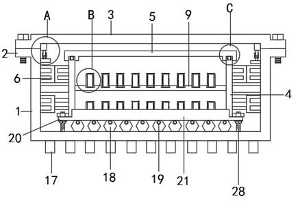
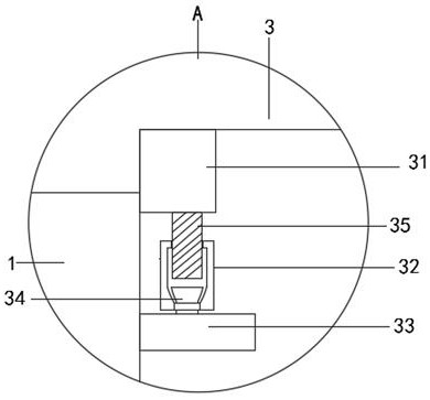
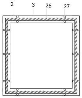
[0029] Refer to the attached Figure 1-7 , a battery pack structure with a high sealing level for new energy electric vehicles in this embodiment, including an outer box 1, an inner box 4, a battery box 11 and a branch pipe 25, and the bottom of the outer box 1 is provided with The extended sealing edge 2 of equal width, the bottom of the outer box 1 is fixed with a rectangular cooling plate 17, the extending sealing edge 2 is provided with a placement groove 26 and an internal thread hole 27, and the top of the extending sealing edge 2 is connected by bolts The outer box cover 3, the inner box 4 is provided in the inner cavity of the outer box 1, and the top of the inner box 4 is provided with a "mouth" shaped groove 15, and the inside of the "mouth" shaped groove 15 A "mouth"-shaped rubber sealing strip 16 is provided, an inner box cover 5 is provided above the inner box 4, the inner box cover 5 is integrally formed with a clamping plate 14 at the bottom of the body cover 5 ...
Embodiment 2
[0038] Refer to the attached Figure 8 The difference from Example 1 is that the bottom of the outer box 1 is plugged with a water tank 29, a rectangular sealing plug 30 is arranged between the outer wall of the outer box 1 and the inner wall of the water tank 29, and the bottom of the outer box 1 is at a distance of The distance between the bottom of the inner cavity of the water tank 29 is 2-4cm, preferably 3cm.
[0039] The specific implementation scenarios are:
[0040] When using the present invention, the heat dissipation pipe 18 is installed on the inner wall of the outer box body 1, the branch liquid injection port 19 on the heat dissipation pipe 18 is connected with the main pipe 22 with the branch pipe 25, and the main pipe 22 is installed on the inner wall of the outer box body 1 and make the height of the outer box 1 higher than the heat dissipation pipe 18, inject cooling liquid into the main pipe 22 through the main liquid injection port 23 on the main pipe 22, ...
PUM
 Abstract
Description
Claims
Application Information
 - R&D
- Intellectual Property
- Life Sciences
- Materials
- Tech Scout
- Unparalleled Data Quality
- Higher Quality Content
- 60% Fewer Hallucinations
Browse by: Latest US Patents, China's latest patents, Technical Efficacy Thesaurus, Application Domain, Technology Topic, Popular Technical Reports.
© 2025 PatSnap. All rights reserved.Legal|Privacy policy|Modern Slavery Act Transparency Statement|Sitemap|About US| Contact US: help@patsnap.com


