Suction type anesthesia machine for general anesthesia

A general anesthesia and anesthesia machine technology, applied in the field of anesthesia machines, can solve the problem of slow exhaust gas discharge, and achieve the effect of reducing the amount of exhaust gas, reducing the content of exhaust gas, and reducing adverse effects

Inactive Publication Date: 2022-03-18
信阳市中心医院
View PDF0 Cites 1 Cited by
  • Summary
  • Abstract
  • Description
  • Claims
  • Application Information

AI Technical Summary

Problems solved by technology

[0005] The purpose of the present invention is to drive the dehumidification drive gear to rotate through the drive shaft, and the mutual cooperation between the dehumidification drive gear and the driven gear makes the reciprocating swing of the telescopic sleeve connected to the dehumidification sponge clean the water vapor on the inner wall of the mask. Drive the antibacterial slave gear to rotate, so that the expansion box on the rotating frame and the cleaning sponge on the outside of the cleaning plate can absorb the water vapor at the connection between the intake pipe, exhaust pipe and the mask, and prevent the growth and adhesion of bacterial dust

Method used


Image

  • Suction type anesthesia machine for general anesthesia
  • Suction type anesthesia machine for general anesthesia
  • Suction type anesthesia machine for general anesthesia

Examples


Embodiment 1

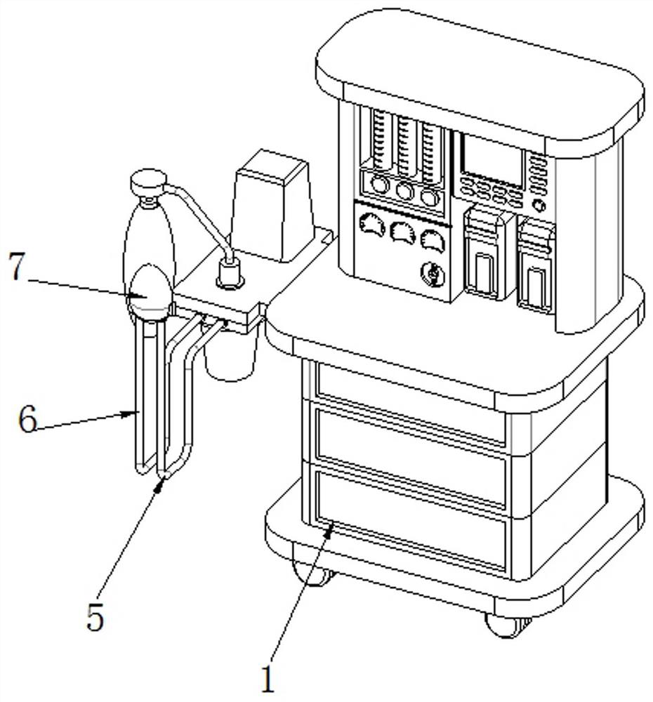
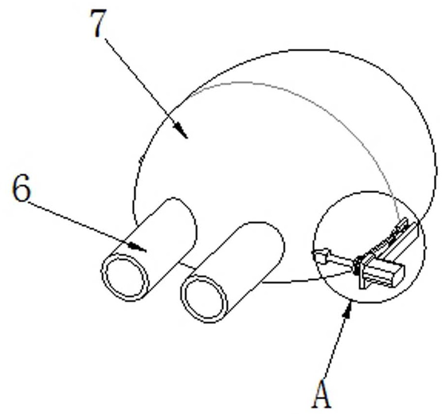
[0038] see Figure 1-6 As shown, an inhalation anesthesia machine for general anesthesia includes an anesthesia machine body 1, an air intake pipe 5, an exhaust pipe 6 and a mask 7, an air intake pipe 5 is connected to one side of the upper surface of the anesthesia machine body 1, and an anesthesia machine body 1 The side of the upper surface close to the intake pipe 5 is connected with an exhaust pipe 6, and the end of the exhaust pipe 6 away from the anesthesia machine body 1 is connected with a mask 7;

[0039] When the inhalation anesthesia machine is working, the mask 7 is connected to the mouth and nose of the patient, and the inlet pipe 5 and the exhaust pipe 6 are connected with one-way valves, so that only the atomized anesthetic can be carried out at the inlet pipe 5 Considering the circulation at position 7 of the mask, the position at exhaust pipe 6 can only circulate the patient’s exhaled exhaust gas. When the patient is inhaling, the one-way valve at position 6 ...

Embodiment 2

[0044] see Figure 7-9 As shown, the inside wall of the mask 7 is provided with an antibacterial mechanism 3 near the position of the exhaust pipe 6. The antibacterial mechanism 3 includes a driven shaft 31. The position corresponding to the intake pipe 5 and the exhaust pipe 6 on the side is connected with the antibacterial slave gear 36, and the inner wall of the intake pipe 5 and the exhaust pipe 6 is provided with a chute 35 near the position of the driven rotating shaft 31, and the intake pipe 5 and the exhaust pipe 6. A supporting frame 32 is connected to the inner side wall close to the chute 35, and a rotating frame 310 is connected to the middle position of the outer side wall of the supporting frame 32 through a connecting shaft 37. The end of the connecting shaft 37 away from the supporting frame 32 is connected to an antibacterial driving gear 33. , the antibacterial driving gear 33 and the antibacterial secondary gear 36 are perpendicular to each other and are fit...

Embodiment 3

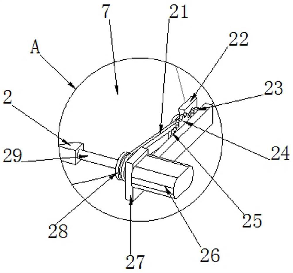
[0048] see Figure 10As shown, the outer wall of the face mask 7 is provided with an exhaust mechanism 4 near the position of the intake pipe 5, and the exhaust mechanism 4 includes an exhaust runner 49, and the outer wall of the drive shaft 29 is connected with an exhaust outlet corresponding to the exhaust runner 49. The main runner 41, the exhaust main runner 41 is connected with the exhaust slave runner 49 through the transmission belt 21, and the outer wall of the mask 7 is connected with a reciprocating screw 44 through the exhaust support seat 48 corresponding to the exhaust slave runner 49, The outer wall of the reciprocating lead screw 44 is slidably connected with a reciprocating plate 43, and the two sides of the outer wall of the reciprocating plate 43 are connected with telescopic hoses 46. Valve, so that the flexible hose 46 can only inhale from the end of the exhaust pipe 6 close to the mask 7, and can only exhaust from the end of the exhaust pipe 6 away from th...


PUM


Abstract

The invention relates to an anaesthesia machine technology, in particular to an inhalation type anaesthesia machine for general anesthesia, which is used for solving the problems that water vapor in a mask is gathered into water drops to drip and then enters the trachea of a patient along with breathing to cause discomfort, and the anaesthesia effect is affected due to the fact that more water vapor easily breeds bacteria and the exhaust speed of waste gas is low at the position of a mask connecting port. Comprising an anaesthesia machine body, an air inlet pipe, an exhaust pipe and a mask. A dehumidification driving gear is driven by a driving shaft to rotate, the dehumidification driving gear is matched with a driven gear, so that water vapor on the inner wall of a mask is cleaned through reciprocating swing of a telescopic sleeve connected with a dehumidification sponge, and a bacteriostatic driven gear is driven by the driving shaft to rotate; the cleaning sponge on the rotating frame can absorb water vapor at a connector of the mask, bacteria and dust are prevented from being bred and attached to the connector, the reciprocating lead screw is driven by the driving shaft to rotate, and waste gas exhaled by a patient in the mask is rapidly transmitted into an exhaust pipe through the telescopic hose.

Description

technical field [0001] The invention relates to anesthesia machine technology, in particular to an inhalation anesthesia machine for general anesthesia. Background technique [0002] The anesthesia machine sends the anesthetic into the alveoli of the patient through a mechanical circuit, forming a partial pressure of the anesthetic gas, which diffuses into the blood, and directly inhibits the central nervous system, thereby producing the effect of general anesthesia. The anesthesia machine is a semi-open anesthesia device. [0003] In the prior art, when the mask rolls on the patient's mouth and nose to guide the atomized anesthetic, the exhaust gas exhaled by the patient carries a certain amount of heat. In the case of condensation, the water vapor in the exhaust gas condenses into small water droplets and adheres to the inner wall of the mask. With the increase of the attached small water droplets, the small water droplets are easy to gather into water droplets and fall. ...

Claims


Application Information

Patent Timeline
IPC IPC(8): A61M16/01A61M16/06A61M16/08
CPCA61M16/01A61M16/06A61M16/0003A61M16/0808
Inventor 左丹丹姜蕊
Owner 信阳市中心医院
Why Eureka
Try Eureka