Concave edging machining hard alloy chopper convenient to replace

A technology that is easy to replace and hard alloy, used in the field of concave rolling processing carbide rivets, can solve the problems of affecting the efficiency of tool replacement, cumbersome replacement, time-consuming and laborious tool searching, etc., and achieve fast and accurate adjustment of the installation height. , Improve the processing efficiency, the effect of convenient and quick installation

Active Publication Date: 2022-03-18
HEYUAN YONGXING CEMENTED CARBIDE
View PDF8 Cites 0 Cited by
  • Summary
  • Abstract
  • Description
  • Claims
  • Application Information

AI Technical Summary

Problems solved by technology

[0005] However, when the tool in the above technology is replaced, it is necessary to search for the replaced tool time-consumingly and laboriously, and the installation height needs to be adjusted according to the length of the tool. It is cumbersome and affects the efficiency of tool replacement

Method used


Image

  • Concave edging machining hard alloy chopper convenient to replace
  • Concave edging machining hard alloy chopper convenient to replace
  • Concave edging machining hard alloy chopper convenient to replace

Examples


Embodiment 1

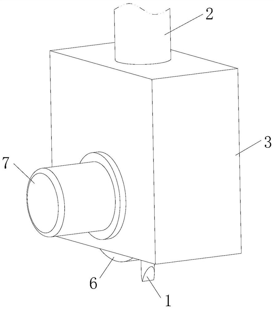
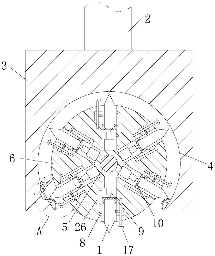
[0033] see Figure 1-Figure 2 As shown, a conveniently replaceable concave-shaped milling carbide riving knife described in the embodiment of the present invention includes a body 1; it also includes a working column 2 on the machine tool, and the bottom end of the working column 2 is connected with a switch block 3, an arc-shaped switching cavity 4 is provided on the bottom surface of the switching block 3, and a cylindrical rotating column 6 is connected to the inside of the switching cavity 4 through a rotating rod 5, and the side wall of the switching block 3 is installed with A motor 7 connected to one end of the rotating rod 5, the other end of the rotating rod 5 is provided with a fixed assembly capable of positioning it, and a set of storage chambers 8 are provided on the side wall of the rotating rod 6, and the storage chamber 8 A No. 1 push rod 9 is installed inside the No. 1 push rod 9, and the end of the No. 1 push rod 9 is connected with a slide plate 10, and the ...

Embodiment 2

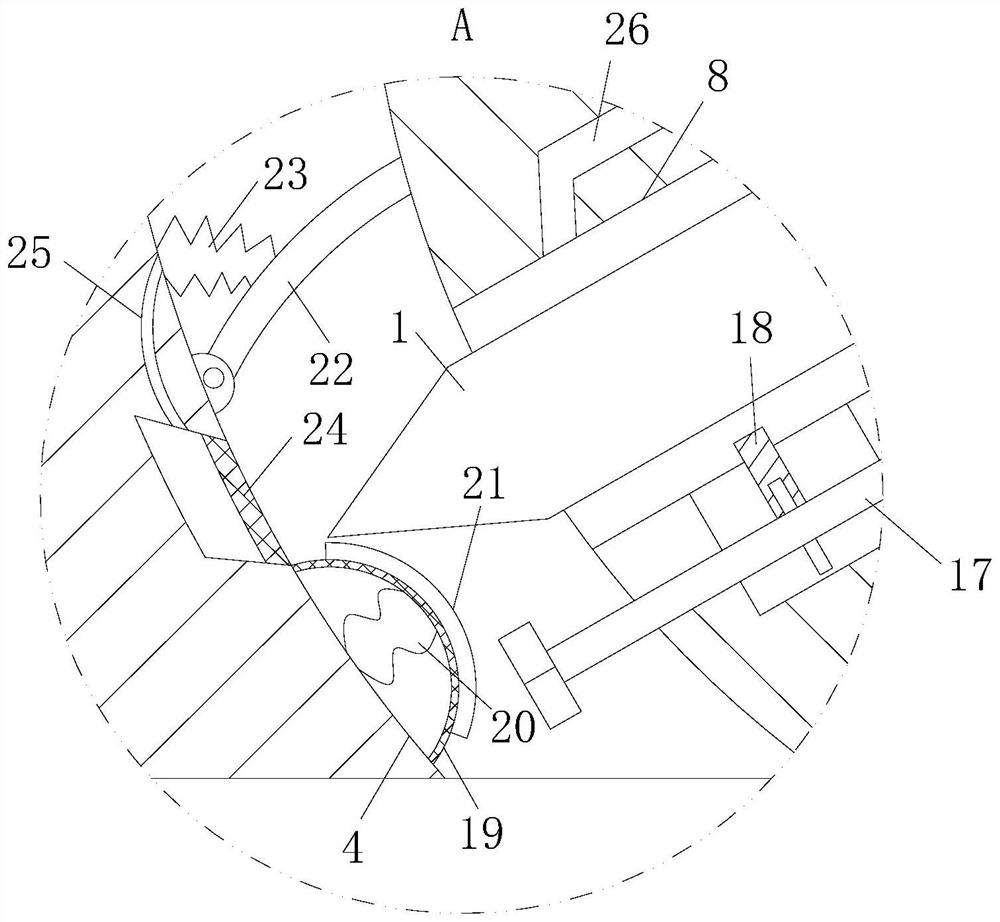
[0040] Such as Figure 6-Figure 7 As shown in Comparative Example 1, another embodiment of the present invention is: the inside of the storage cavity 8 is connected with a ring-shaped slip ring 27 through a bracket, and the slip ring 27 is slidably connected with a slider 28, so The inside of the slider 28 is provided with an airflow channel 29, and a hose 30 is connected between one end of the airflow channel 29 and the end of the cleaning groove 26 at the outer end of the storage chamber 8, and the slider 28 is installed on one side facing the body 1. There is No. 1 nozzle 31 communicated with the air passage 29, and No. 2 nozzle 32 is installed on the side wall of the slide block 28 away from the support. The side wall of the cleaning tank 26 is tangent to the side wall; the gas extruded from the cleaning tank 26 can be sprayed from the two nozzles through the hose 30, so that the airflow tangential to the slip ring 27 sprayed from the second nozzle 32 can drive the slider ...


PUM


Abstract

The invention belongs to the technical field of turning tools, and particularly relates to a concave edging machining hard alloy chopper convenient to replace. The device further comprises a working column and a switching block, a switching cavity is formed in the bottom face of the switching block, a rotating column is rotationally connected to the interior of the switching cavity through a rotating rod, a set of storage cavities are formed in the side wall of the rotating column, first push rods are installed in the storage cavities, and sliding plates are connected to the ends of the first push rods. The outer end of the sliding plate is in threaded connection with the end part of the body; the mounting height of the body can be adjusted more accurately and efficiently, so that the body is mounted more conveniently and quickly, quick switching of the body can be realized by mounting a plurality of chopper bodies in the switching cavity in advance, the machining efficiency of a workpiece is improved, and the machining cost is reduced. And meanwhile, the pre-installed body can be effectively stored through the switching cavity, and the adverse effect of external dust and impurities on the body is reduced.

Description

technical field [0001] The invention belongs to the technical field of turning tools, and in particular relates to a conveniently replaceable concave-shaped rolling tool for machining cemented carbide riving knife. Background technique [0002] A turning tool is a tool with a cutting part for turning. The turning tool is one of the most widely used tools in cutting. The working part of the turning tool is the part that generates and processes chips, including the cutting edge, breaking chips Structural elements such as the structure of rolling or rolling, the space for chip removal or chip storage, the passage of cutting fluid, etc., and the concave rolling machined carbide splitting knife is a kind of turning tool. When the workpiece is processed, the chopper needs to be replaced according to the type of the workpiece or the different processing positions of the same workpiece. [0003] A Chinese patent with a publication number of CN209766364U discloses a fast-changing ji...

Claims


Application Information

Patent Timeline
IPC IPC(8): B23B29/24B23B29/32
CPCB23B29/246B23B29/32
Inventor 张承熙
Owner HEYUAN YONGXING CEMENTED CARBIDE
Why Eureka
Try Eureka