
Multifunctional processing equipment for ship shafting flange
A kind of processing equipment and multi-functional technology, applied in the field of ship parts processing, can solve the problems of processing inconvenience, achieve the effect of improving processing quality, avoiding drill bit damage, and simple and reliable operation
- Summary
- Abstract
- Description
- Claims
- Application Information
AI Technical Summary
Problems solved by technology
Method used
Image

Examples
Embodiment
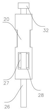
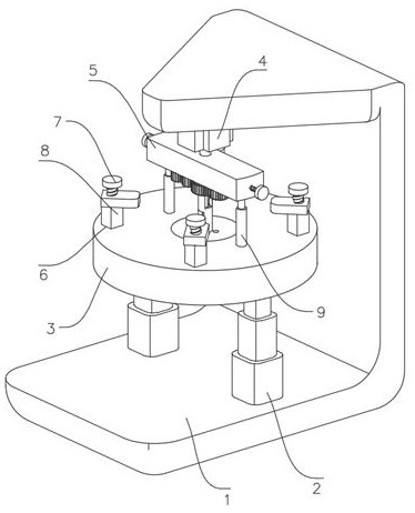
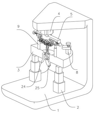
[0029] refer to Figure 1-10 , the processing equipment of the multifunctional ship shafting flange, including a base 1, the upper end of the base 1 is fixed with a lifting rod 2, the upper end of the lifting rod 2 is fixed with a processing table 3, the top of the base 1 is fixed with a motor 4, the motor The output shaft of 4 is fixed with a turntable 5, the bottom of the turntable 5 is connected with two drill bits 9 through two sets of adjustment mechanisms, the upper end of the processing table 3 is provided with a plurality of pressing grooves 6, and the inside of the pressing groove 6 is provided with a pressing mechanism , The upper end of the processing table 3 is fixed with a fixed sleeve 20, the upper side wall of the fixed sleeve 20 is fixed with a central gear 21 that drives the drill bit 9 to rotate, and the inside of the processing table 3 is provided with a liquid injection mechanism.
[0030] The adjustment mechanism includes an adjustment cavity 10 set inside...
PUM
 Abstract
Description
Claims
Application Information