Vibration suppression robot using multi-peak input shaping method and control method thereof
A technology for input shaping and robotics, applied in the direction of program control manipulators, manipulators, manufacturing tools, etc., can solve problems such as the inability to suppress residual oscillation of multi-modal flexible systems, and the mechanical equipment that cannot effectively face multiple motion trajectories. Residual swing, improved control positioning accuracy, strong anti-interference ability
- Summary
- Abstract
- Description
- Claims
- Application Information
AI Technical Summary
Problems solved by technology
Method used
Image
Examples
Embodiment 1
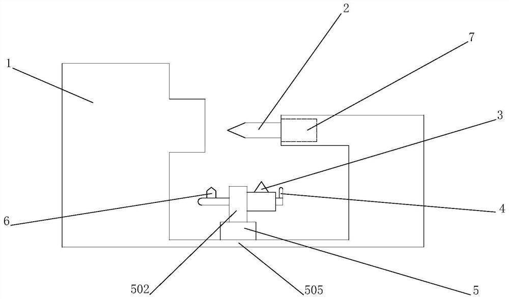
[0045] S1: Using the automatic processing mode, the user sets the automatic movement setting parameters of the machine body 1 in advance through the integrated display terminal, and the control system converts the automatic movement setting parameters into the movement trajectory of the moving part 2, and sends them in advance according to different movement trajectories Input shaping algorithm instructions, wherein the uniform velocity motion stage corresponds to the secondary system input shaping algorithm, the uniform acceleration motion stage corresponds to the tertiary system input shaping algorithm, and the variable acceleration motion stage corresponds to multiple system input shaping algorithms;
[0046] S2: The trajectory prediction module calculates and simulates the trajectory of the moving part 2 in the shaping stage according to the automatic motion setting parameters and the shaping command, and generates a virtual three-dimensional motion trajectory model in the c...
Embodiment 2
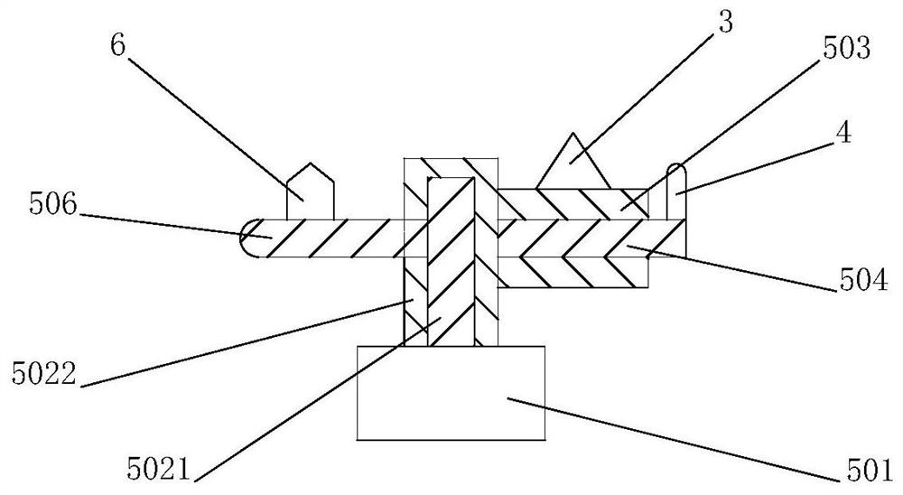
[0048] S1: Using manual processing mode, after the moving part 2 starts processing, the laser rangefinder 3 measures the movement distance of the moving part 2 recognition point every 0.5 seconds, and the three-dimensional camera 6 measures the angle change value and movement of the moving part 2 recognition point every 0.5 seconds The change value of the moving speed of the identification point of the component 2 every 0.5 seconds, wherein the laser rangefinder 3, the grabbing camera 4, and the three-dimensional camera 6 move with the gimbal 5 to grab the identification point, and the control system controls the guide rail 505, the main shaft 502, the side The axis A503, the side axis B504, and the side axis C506 move relative to each other, so that the capture interface of the capture camera 4 and the 3D camera 6 always covers the recognition point, so that the laser rangefinder 3 can detect the moving part 2;
[0049] S2: The control system calculates the actual motion traje...
PUM
 Abstract
Description
Claims
Application Information
 - R&D
- Intellectual Property
- Life Sciences
- Materials
- Tech Scout
- Unparalleled Data Quality
- Higher Quality Content
- 60% Fewer Hallucinations
Browse by: Latest US Patents, China's latest patents, Technical Efficacy Thesaurus, Application Domain, Technology Topic, Popular Technical Reports.
© 2025 PatSnap. All rights reserved.Legal|Privacy policy|Modern Slavery Act Transparency Statement|Sitemap|About US| Contact US: help@patsnap.com


