Plastic shell conveying batten and shell buckling machine

A technology of conveying strips and conveying chains, which is applied in the field of plastic casing conveying slats and shell buckling machines, which can solve the problems of poor fixing effect of plastic casings, and achieve the effects of structural improvement, strong practicability, and structural optimization

Pending Publication Date: 2022-03-18
DIER PHARMA MACHINERY LLC HEILONGJIANG +1
View PDF0 Cites 0 Cited by
  • Summary
  • Abstract
  • Description
  • Claims
  • Application Information

AI Technical Summary

Problems solved by technology

[0005] The object of the present invention is to provide a molded case conveying slat and a shell buckle machine to solve the problem of poor fixing effect of the plastic case in the above-mentioned existing slat structure

Method used


Image

  • Plastic shell conveying batten and shell buckling machine
  • Plastic shell conveying batten and shell buckling machine
  • Plastic shell conveying batten and shell buckling machine

Examples


Embodiment 1

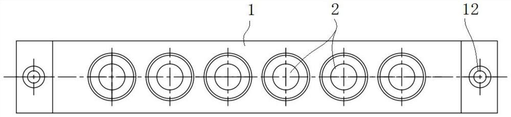
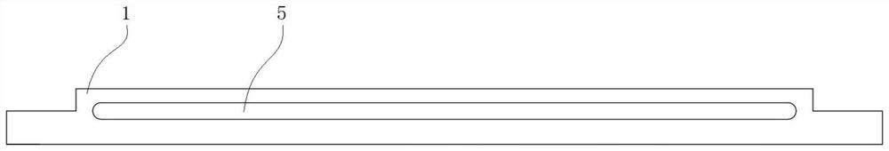
[0051] This embodiment provides a molded case conveying slat 100 , which includes a slat body 1 and a reinforcing rubber strip 4 , and a plurality of stepped holes 2 are opened on the slat body 1 , and any one of the stepped holes 2 runs through the thickness direction of the slat body 1 set, and the large hole 21 of any step hole 2 is used to load the plastic case 7, and the small hole 23 of any step hole 2 is used to support the plastic case 7; the inner wall of the large hole 21 of any step hole 2 is provided with a concave Groove 3; the reinforcing rubber strip 4 is embedded in the groove 3 and matches with the outer surface of the plastic case 7 to clamp and fix the plastic case 7 to prevent the plastic case 7 from rotating freely. The plastic case 7 is an existing pill loading structure, and is in a standard spherical shape as a whole. It includes a lower plastic case 71 and an upper plastic case 72 snapped to the lower plastic case 71 .

[0052] In this embodiment, the ...

Embodiment 2

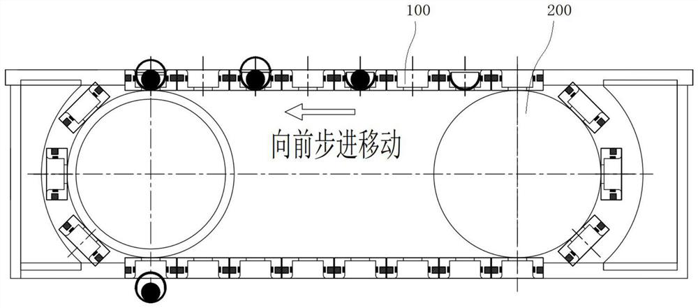
[0061] Such as figure 1 As shown, the present embodiment also proposes a shell buckle machine, which includes a conveying chain 200 and several plastic case conveying slats 100 as described in Embodiment 1; that is, figure 1 Shown in the "forward stepping movement" direction) are installed on the conveyor chain 200 in turn. Both ends of the strip body 1 of any molded case conveying strip 100 are provided with counterbore holes 12, which can be fixed with the conveying chain 200 through bolts and other connecting structures.

[0062] Shell buckling machine is a relatively mature technology. Except for the molded shell conveying slat 100, the rest of the structure basically adopts the existing technology, including the lower molded shell 71 insertion component, the pill insertion component, and the upper and lower molded shell compression components. And the power drive mechanism of the conveyor chain 200, etc., wherein the conveyor chain 200 can also be replaced by an outpu...


PUM


Abstract

The invention discloses a plastic shell conveying batten which comprises a batten body and a reinforcing rubber strip, a plurality of step holes are formed in the batten body, any step hole penetrates through the batten body in the thickness direction, a large hole of any step hole is used for loading a plastic shell, and a small hole of any step hole is used for supporting the plastic shell; a groove is formed in the inner wall of a large hole of any stepped hole; and the reinforcing adhesive tape is embedded in the groove and is used for clamping and fixing the plastic shell. The inner wall of the large hole of the stepped hole is provided with the groove, and the reinforcing rubber strip is embedded in the groove, so that the plastic shell can be clamped and fixed, the plastic shell can be prevented from rotating in the stepped hole of the batten in the working process of the shell buckling machine, pills can be conveniently put into the shell buckling machine, the plastic shell can be conveniently buckled, and the shell buckling yield of the shell buckling machine and the stability of the production process are further improved. The invention further provides a shell buckling machine which comprises a conveying chain and the plastic shell conveying batten.

Description

technical field [0001] The invention relates to the field of pharmaceutical machinery, in particular to a molded case conveying slat and a case buckling machine. Background technique [0002] At present, some large honeyed Chinese medicine pills in China use the packaging method of buckling the pills in the plastic case, and then dipping wax on the outside of the plastic case to seal, such as Figure 6 shown. The common buckling machine needs to complete the steps of putting in the lower shell, putting in the pills, putting in the upper shell, and pressing the upper and lower shells on the slats. The slats should not only have the function of conveying, but also have the function of fixing the molded shell. [0003] However, at present, the slats used for fixing and conveying plastic cases are usually made of non-metallic materials. Since the slats have a certain length, the slats will be bent and deformed after a period of use; at the same time, the existing slats are used ...

Claims


Application Information

Patent Timeline
Patent Type & Authority Applications(China)
IPC IPC(8): B65B43/52B65G17/06B65G17/32B65B7/28
CPCB65B43/52B65G17/06B65G17/32B65B7/2842
Inventor 王官连周明丁晓慧崔鹏
Owner DIER PHARMA MACHINERY LLC HEILONGJIANG
Why Eureka
Try Eureka