
Unmanned loading system

A vehicle and on-site technology, applied in the field of unmanned loading system, can solve problems such as high labor intensity, harmful to human body, unsafe, etc., and achieve the effect of reducing accidents, avoiding safety accidents, and accurate and effective positioning

Inactive Publication Date: 2022-03-18
烟台掌控智能科技有限公司
View PDF7 Cites 2 Cited by
  • Summary
  • Abstract
  • Description
  • Claims
  • Application Information

AI Technical Summary

Problems solved by technology

[0003] Based on the retrieval of the above information, it can be seen that this operation has the following disadvantages: Hazardous chemicals themselves are harmful to the human body and need to be climbed every time, which is unsafe, and the labor intensity is high and the efficiency is low
[0004] The improvement of the above problems in the current technology is to change the crane tube to pneumatic motion control, and no one needs to climb the roof. This method only solves the problem that no one needs to climb the roof to release the tube. For this reason, an unmanned loading The system, through the radar scanning target automatic pattern recognition, through the PC automatic calculation of the running track, sends commands to the PLC to control the three-axis angular movement of the robotic arm, accurately locates the target position, realizes the controlled loading, completely liberates manpower, and realizes unmanned loading on site , to truly realize mechanized reduction of personnel, automatic replacement of personnel, and reduce the number of on-site operators in high-risk positions

Method used


Image

  • Unmanned loading system
  • Unmanned loading system
  • Unmanned loading system

Examples


Embodiment 1

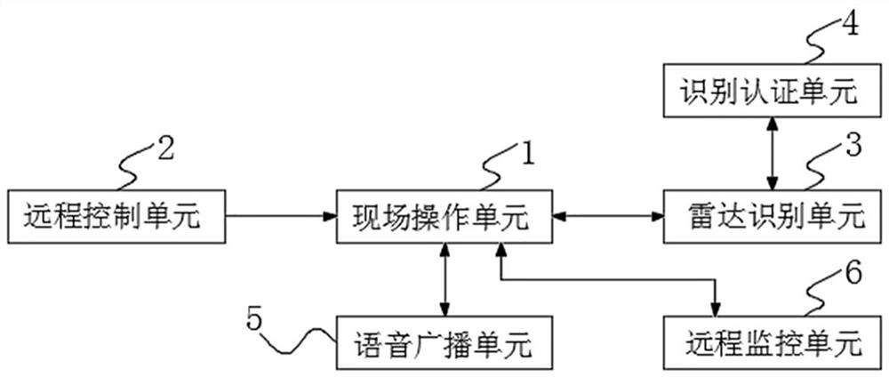
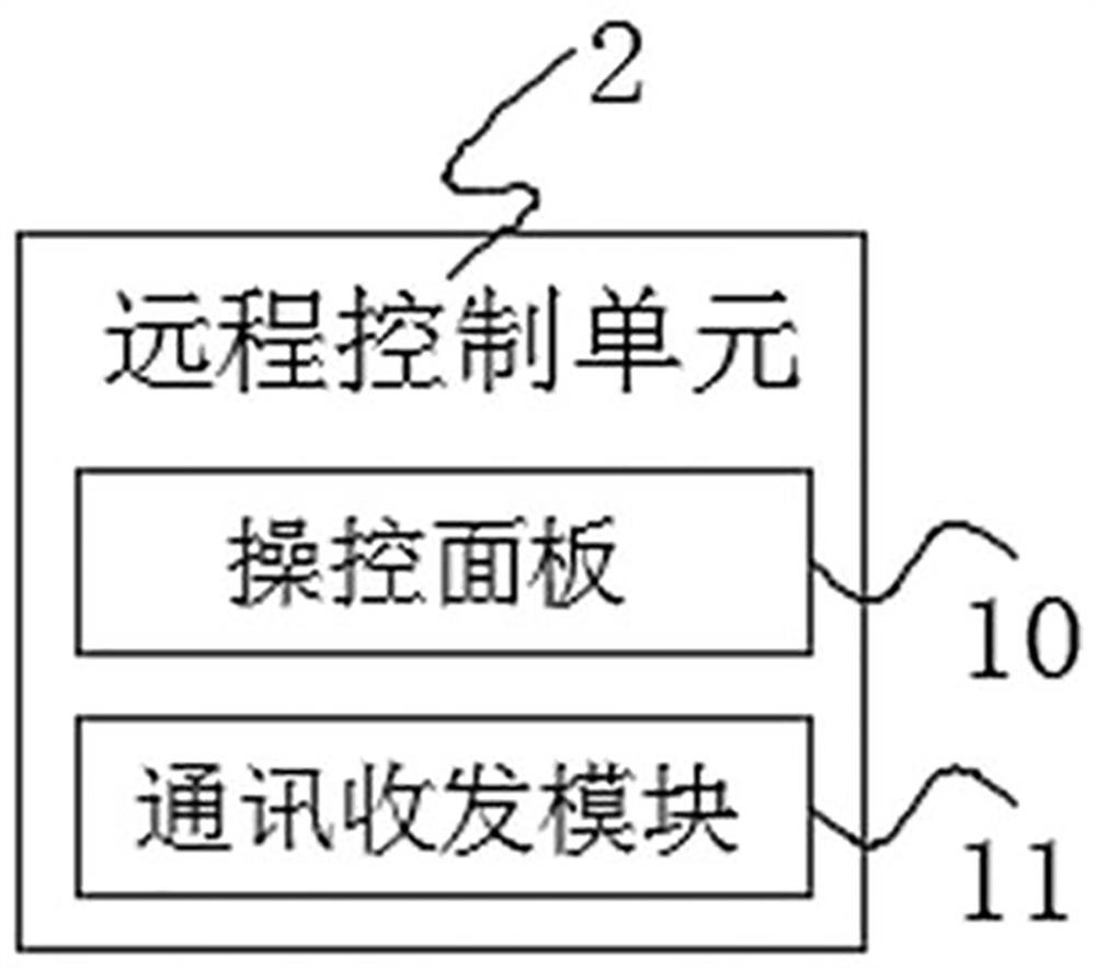
[0039]An unmanned loading system, including an on-site operation unit 1 and a remote control unit 2, the on-site operation unit 1 is used for on-site operation, and the crane tube is controlled by a pneumatic motor to control the mechanical arm to move in the X, Y and Z directions for The remote control unit 2 is docked with the on-site operation unit 1, and the remote control unit 2 is used to remotely control the operation of the air motor. The on-site operation unit 1 is connected with the radar identification unit 3, and the radar identification unit 3 is used to identify the vehicle pipe The position of the nozzle, and obtain the three-dimensional coordinates of the vehicle nozzle, calculate the movement trajectory of the crane pipe, and synchronize the three-dimensional coordinates of the vehicle nozzle and the movement trajectory data to the field operation unit 1, the radar identification unit 3 and the identification and authentication unit 4 Docking, wherein the ident...

Embodiment 2

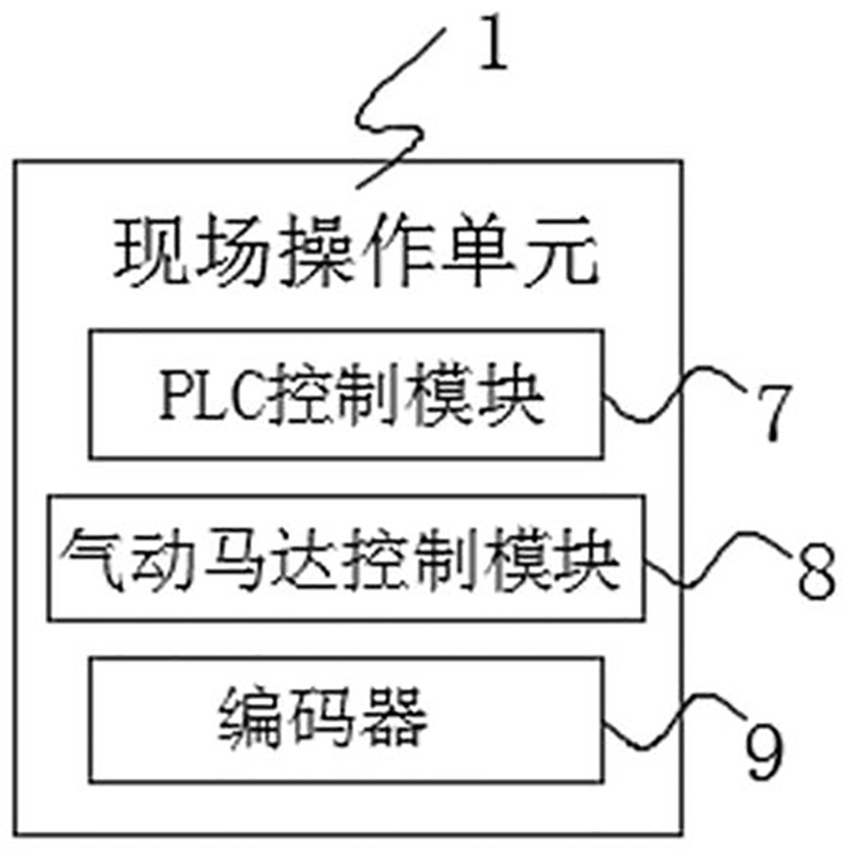
[0041] This embodiment is an improvement of the previous embodiment. An unmanned loading system includes an on-site operation unit 1 and a remote control unit 2. The on-site operation unit 1 is used for on-site operations, and the crane tube is controlled by a pneumatic motor to control the mechanical arm to perform X. , Y and Z direction movement, used to align the nozzle of the vehicle. As a detailed description, the nozzle of the vehicle uses a pneumatic valve to control the opening and closing, and the driver of the vehicle is responsible for opening or closing. When it is opened, the vehicle is in a flame-off state. Before the driver of the vehicle opens the pneumatic valve, it is necessary to complete the identification of the nozzle of the vehicle. Specifically, as attached figure 2 As shown, the field operation unit 1 includes a PLC control module 7, an air motor control module 8 and an encoder 9, wherein the air motor control module 8 is used to drive the mechanical a...


PUM


Abstract

The unmanned loading system comprises an on-site operation unit and a remote control unit, the on-site operation unit is used for on-site operation, a mechanical arm is controlled through a pneumatic motor to control a crane pipe to move in the X direction, the Y direction and the Z direction, the on-site operation unit is used for being aligned with a vehicle pipe opening, and the remote control unit is in butt joint with the on-site operation unit. The invention relates to the technical field of information automation. According to the unmanned loading system, coordinates are obtained through radar image recognition, so that the mechanical arm is controlled to accurately move to achieve unmanned operation, the brand new unmanned loading function is achieved in cooperation with all-purpose card setting of the recognition and authentication unit, digital monitoring is established for enterprises, original and traditional loading operation in the manual lifting hazardous chemical industry is liberated, accidents are reduced, and the working efficiency is improved. Safety accidents are avoided, loading efficiency is improved, manpower is completely liberated, unmanned loading on site is achieved, mechanical labor reduction and automatic labor replacement are truly achieved, and the number of field operating personnel of high-risk posts is reduced.

Description

technical field [0001] The invention relates to the technical field of information automation, in particular to an unmanned loading system. Background technique [0002] At present, 80% of the liquid loading operations in chemical plants are still mainly operated manually by on-site personnel. The specific process of manual operation is that the vehicle is parked in place, the operator puts on the seat belt, puts down the platform ladder, and then moves the crane tube to climb through the ladder. Climb to the top of the tanker, put the crane pipe into the nozzle on the top of the vehicle, then tighten the locking mechanism, go back to the platform through the steps, open the valve to fill the liquid, stop loading after the amount is reached, and manually open the exhaust valve. Drain the remaining liquid, manually put down the step ladder and climb to the top of the vehicle, loosen the locking mechanism, pull out the filling crane tube and return it to its position through t...

Claims


Application Information

Patent Timeline
Patent Type & Authority Applications(China)
IPC IPC(8): B67D7/06B67D7/42B67D7/78
CPCB67D7/06B67D7/42B67D7/78
Inventor 孙洪卿席福强
Owner 烟台掌控智能科技有限公司
Learn More