Wave-dissipating and load-reducing protection device for sea-crossing bridge high pile cap foundation

A technology of high pile caps and protection devices, which is applied in the direction of protection devices, infrastructure engineering, construction, etc., can solve the problems of increasing the difficulty of foundation construction due to the shape of the foundation, large wave loads of facilities, and difficulty in ensuring safety, so as to achieve the purpose of restraining the surface The effect of wave climbing, increasing wave energy dissipation, and simple structure

Active Publication Date: 2022-03-18
SOUTHWEST JIAOTONG UNIV
View PDF3 Cites 3 Cited by
  • Summary
  • Abstract
  • Description
  • Claims
  • Application Information

AI Technical Summary

Problems solved by technology

[0003]Most of the existing wave-absorbing and load-reducing devices face the bridge pier, but the structure of the high pile cap is significantly different from that of the bridge pier, so it is applied to the high pile cap of the cross-sea bridge Basically, the problem of wave absorption and load reduction cannot be completely solved, mainly reflected in: (1) The environment of the foundation of cross-sea bridges is complex, and the optimization of the foundation shape will significantly increase the difficulty of fou

Method used


Image

  • Wave-dissipating and load-reducing protection device for sea-crossing bridge high pile cap foundation
  • Wave-dissipating and load-reducing protection device for sea-crossing bridge high pile cap foundation
  • Wave-dissipating and load-reducing protection device for sea-crossing bridge high pile cap foundation

Examples


Embodiment Construction

[0026] The present invention will be further described below in conjunction with the accompanying drawings and embodiments. It should be noted that, in the case of no conflict, the embodiments in the present application and the technical features in the embodiments can be combined with each other. It should be noted that, unless otherwise specified, all technical and scientific terms used in this application have the same meaning as commonly understood by those of ordinary skill in the art to which this application belongs. The disclosure of the present invention uses "comprises" or "comprises" and other similar words to mean that the elements or objects appearing before the words include the elements or objects listed after the words and their equivalents, without excluding other elements or objects.

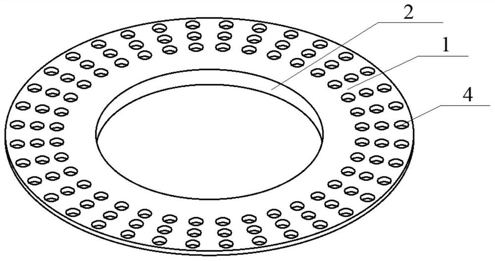
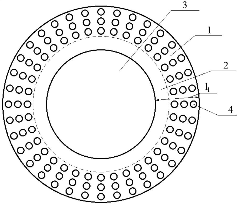
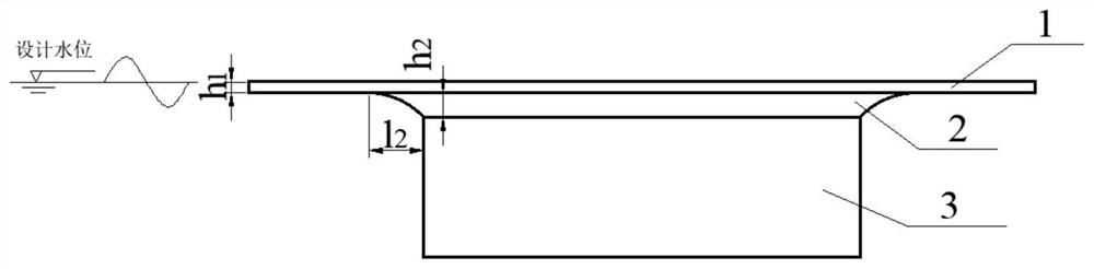
[0027] Such as Figure 1-4 As shown, the present invention provides a protection device for wave dissipation and load reduction for high pile cap foundations of cross-sea brid...


PUM


Abstract

The invention discloses a wave-dissipating and load-reducing protection device for a sea-crossing bridge high pile cap foundation, which comprises an annular protection plate and a supporting part, a plurality of uniformly distributed through holes are formed in the annular protection plate, and the through hole rate of the through holes in the annular protection plate is 35%-55%; the annular protective plate is vertically and fixedly connected to the outer surface of the high pile cap, the top face of the annular protective plate is flush with the designed water level, the thickness of the annular protective plate is 1/8-1/5 of the designed wave height, and the length of the annular protective plate is 1/20-1/10 of the designed wave length; one end of the supporting component is connected with the lower surface of the ring type protection plate, and the other end of the supporting component is connected with the high pile cap. According to the invention, the perforated ring-type protective plates and the supporting parts can be utilized to obviously improve the lateral wave load of the high-rise pile cap from the three mechanisms of inhibiting the climbing of surface waves, changing the wave form and increasing the energy dissipation of the wave, a certain ship collision prevention capability is provided for the high-rise pile cap foundation of a sea-crossing bridge, and technical support is provided for sea-crossing traffic engineering.

Description

technical field [0001] The invention relates to the technical field of sea-crossing bridge engineering, in particular to a wave dissipation and load-reducing protection device for high pile cap foundations of sea-crossing bridges. Background technique [0002] Cross-sea bridges are the key nodes and throats of cross-sea transportation infrastructure projects. my country's coastline is 32,000 kilometers long, and the construction potential of cross-sea transportation projects is huge. Especially in the southeast coastal economic belt, there is a wide demand for cross-sea bridges. Compared with inland bridges, the construction environment of sea-crossing bridges is harsher, and one of the most prominent problems is wave invasion. The completed projects show that under the influence of waves, the hydrodynamic load of the bridge foundation in the marine environment is more than 10 times that of the inland river environment. For example, the Pingtan Strait Highway-Railway Bridge...

Claims


Application Information

Patent Timeline
IPC IPC(8): E02B3/26E02D31/06E02D27/14
CPCE02B3/26E02D31/06E02D27/14Y02A30/30
Inventor 遆子龙王艳凤周远洲
Owner SOUTHWEST JIAOTONG UNIV
Why Eureka
Try Eureka