Blow-down valve and disassembly-free filter

A sewage valve and valve core technology, which is applied to fixed filter element filters, filtration separation, valve devices, etc., can solve the problems of not installing a cleaning mechanism and a sewage valve at the same time, increasing the risk of leakage, complex structure, etc., and achieving a simple structure. , low cost, small size effect

Inactive Publication Date: 2022-03-18
湖南同能机电科技有限公司
View PDF2 Cites 0 Cited by
  • Summary
  • Abstract
  • Description
  • Claims
  • Application Information

AI Technical Summary

Problems solved by technology

[0002] The traditional filter does not have the function of dismantling and cleaning the filter screen, and some technologies have been improved, but the cleaning and sewage separation mode is adopted, such as: 201610110363.X, a double-layer Y-shaped hand filter, 201820452951.6, an air source heat pump In the above-mentioned prior art, the cleaning mechanism of the rotary brush is used to clean the container or filter, and the cleaning of the inner wall is realized by rotating the brush repeatedly, and a special sewage valve is set for sewage discharge, that is, cleaning Two sets of devices are used to realize the discharge and sewage discharge; the structure is complex and the volume is large
And for the DN20 small filter, there is no space to install the cleaning mechanism and the blowdown valve at the same time
2020225349489 A sewage valve suitable for cleaning the filter screen. Although the cleaning brush and the brush rod are combined with the valve, the movement of the cleaning brush and the brush rod is not related to the action of the valve. The two sealing parts, that is, the sealing of the rotary core and the valve core, increase the risk of leakage, the structure is complex, and the reliability is poor

Method used


Image

  • Blow-down valve and disassembly-free filter
  • Blow-down valve and disassembly-free filter
  • Blow-down valve and disassembly-free filter

Examples


Embodiment 1

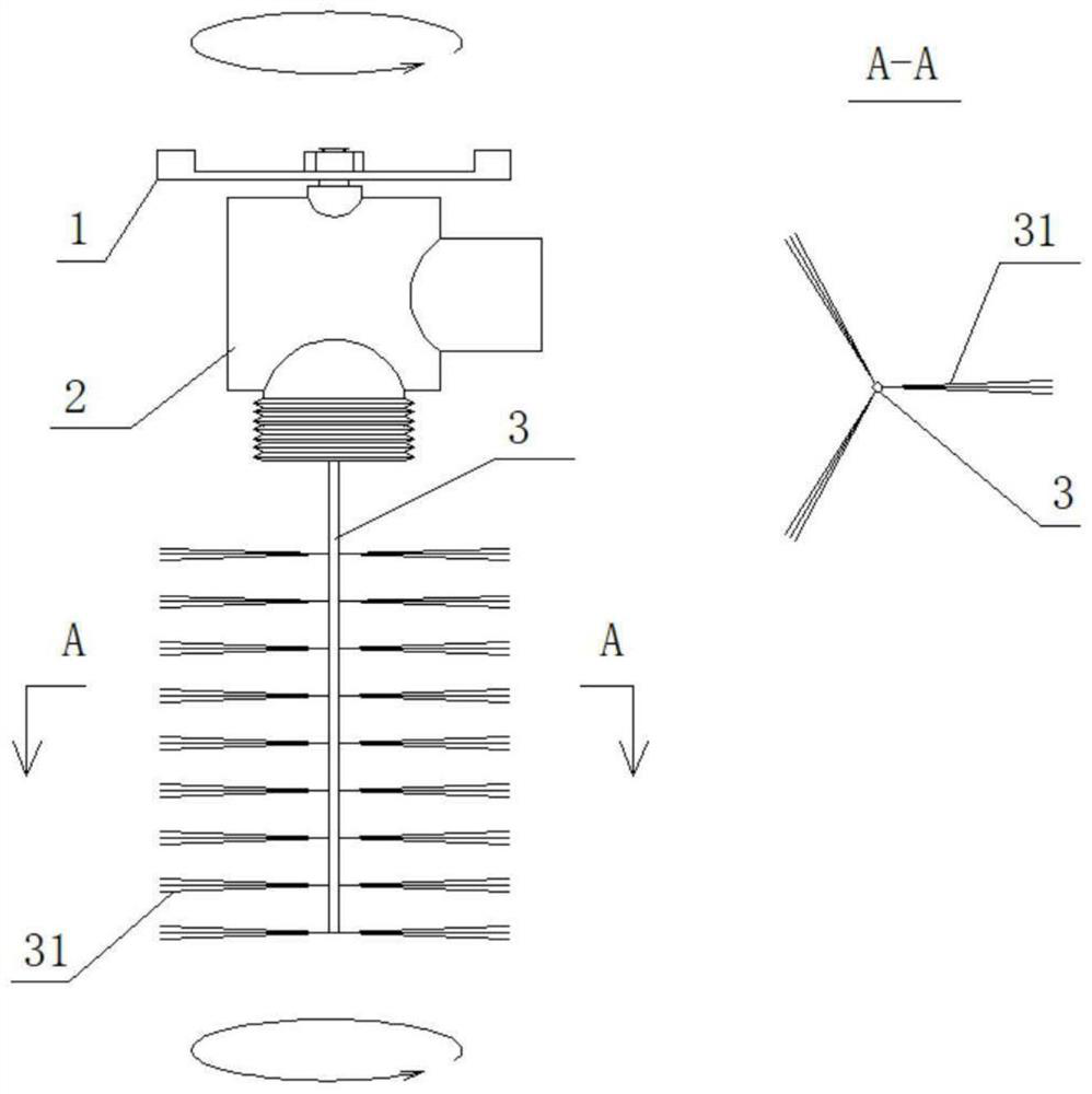
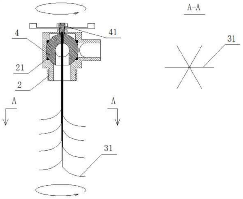
[0054] Embodiment 1: see figure 1 , Figure 4-5 , a blowdown valve, including a right-angle ball valve and a cleaning mechanism, the right-angle ball valve includes a valve body 2, a valve core gasket 21 and moving parts. The moving parts include a handle 1, a spool connecting rod 41, and a spool 4. One end of the spool connecting rod 41 is connected to the handle 1 outside the valve body, and the other end is connected to the spool 4, wherein the spool connecting rod 41, the spool 4 and the The inlet channel of the valve body 2 is coaxial, and the handle 1 drives the valve core 4 to rotate in the valve body 2 through the valve core connecting rod 41; the movement of the valve core 4 can make the outlet channel of the valve body 2 open and close.

[0055] The cleaning mechanism includes a brush rod 3 and a brush head 31, one end of the brush rod 3 is connected to the valve core 4 or the valve core connecting rod 41, and the other end extends to the outside of the valve body 2...

Embodiment 2

[0056] Embodiment 2: The difference with Embodiment 1 is that, see figure 2 , the cleaning mechanism adopts the curved elastic brush 31 with the brush rod and the brush head integrated, and the curved elastic brush 31 composed of several L-shaped steel wires gathers together at one end, and is connected with the valve core 4 or the valve core connecting rod 41. The other end spreads out to the outside of the valve body 2 . The other end of the elastic brush spreads out and contacts the inner wall of the barrel-shaped container to be cleaned.

Embodiment 3

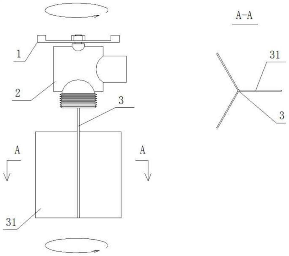
[0057] Embodiment 3: The difference with Embodiment 1 is that, see image 3 , The brush head 31 adopts a plate-shaped or shovel-shaped structure, such as a rubber or silicone scraper.


PUM


Abstract

The invention discloses a blow-down valve and a disassembly-free filter. The blow-down valve comprises a valve body and a driving mechanism for driving a valve element in the valve body to rotate; the device further comprises a cleaning brush. The cleaning brush is fixed to the driving mechanism or the valve element, and when the driving mechanism acts, the cleaning brush is in linkage with the driving mechanism and can clean the container wall or the pipe wall or the filter screen. The blow-down valve and the disassembly-free filter are easy to implement and convenient to use.

Description

technical field [0001] The invention belongs to the field of self-cleaning valves, and relates to a sewage valve and a non-dismantling filter. Background technique [0002] The traditional filter does not have the function of cleaning the filter screen without dismantling, and some technologies have been improved, but the cleaning and sewage separation mode is adopted, such as: 201610110363.X, a double-layer Y-shaped hand filter, 201820452951.6, an air source heat pump In the above-mentioned prior art, the cleaning mechanism of the container or filter adopts the cleaning mechanism of the rotary brush, and the cleaning of the inner wall is realized by rotating the brush repeatedly, and a special sewage valve is set for sewage discharge, that is, cleaning Two sets of devices are used to realize the discharge and sewage discharge; the structure is complex and the volume is large. And for the DN20 small filter, there is no room for installing the cleaning mechanism and the blow...

Claims


Application Information

Patent Timeline
Patent Type & Authority Applications(China)
IPC IPC(8): F16K5/06F16K5/08B08B9/087B01D35/02B01D29/64B01D29/35
CPCF16K5/06F16K5/08B01D35/02B01D29/35B01D29/6415B08B9/087
Inventor 谢梦刘文明童乙伦
Owner 湖南同能机电科技有限公司
Why Eureka
Try Eureka