Garbage dehydrator capable of recycling heat energy

A garbage dehydration and thermal energy technology, which is applied in dryers, lighting and heating equipment, local agitation dryers, etc., can solve the problems of reducing garbage combustion efficiency, energy waste, and non-recycling of heat, so as to improve the utilization rate of thermal energy, The effect of increasing residence time and improving efficiency

Pending Publication Date: 2022-03-18
广东肇庆天盛泰景环保科技有限公司
View PDF5 Cites 0 Cited by
  • Summary
  • Abstract
  • Description
  • Claims
  • Application Information

AI Technical Summary

Problems solved by technology

However, the high-temperature tail gas discharged from the waste incineration power plant in the prior art does not recycle the heat in the tail gas, thus causing a huge waste of energy, and before the waste is incinerated, the waste is mixed with some leaves, fruit peels, etc. Moisture in the garbage, thus reducing the efficiency of burning the garbage

Method used


Image

  • Garbage dehydrator capable of recycling heat energy
  • Garbage dehydrator capable of recycling heat energy
  • Garbage dehydrator capable of recycling heat energy

Examples


Embodiment 1

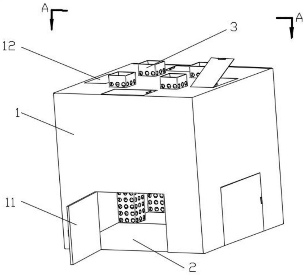
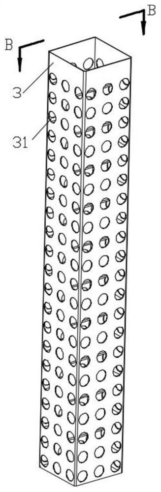
[0023] refer to Figure 1-4 A thermal energy recycling garbage dehydrator shown includes: a housing 1, a deflector 2 and four air guide cylinders 3, wherein the deflector 2 is arranged at the bottom of the housing 1, and the deflector 2 is provided with There is a smoke inlet 21. Four air guiding cylinders 3 are all arranged inside the housing 1, and the top of each air guiding cylinder 3 runs through the top of the housing 1, and the bottom end of each air guiding cylinder 3 is respectively connected to a smoke opening 21 Corresponding settings.

[0024] The side walls around the housing 1 are respectively provided with a discharge door 11, and each discharge door 11 is close to the deflector 2, and the position of the discharge door 11 is lower to facilitate the discharge of dried articles. The top of the casing 1 is provided with four feed doors 12, and each feed door 12 is set corresponding to a discharge door 11 respectively, and a certain distance is kept between the fo...

Embodiment 2

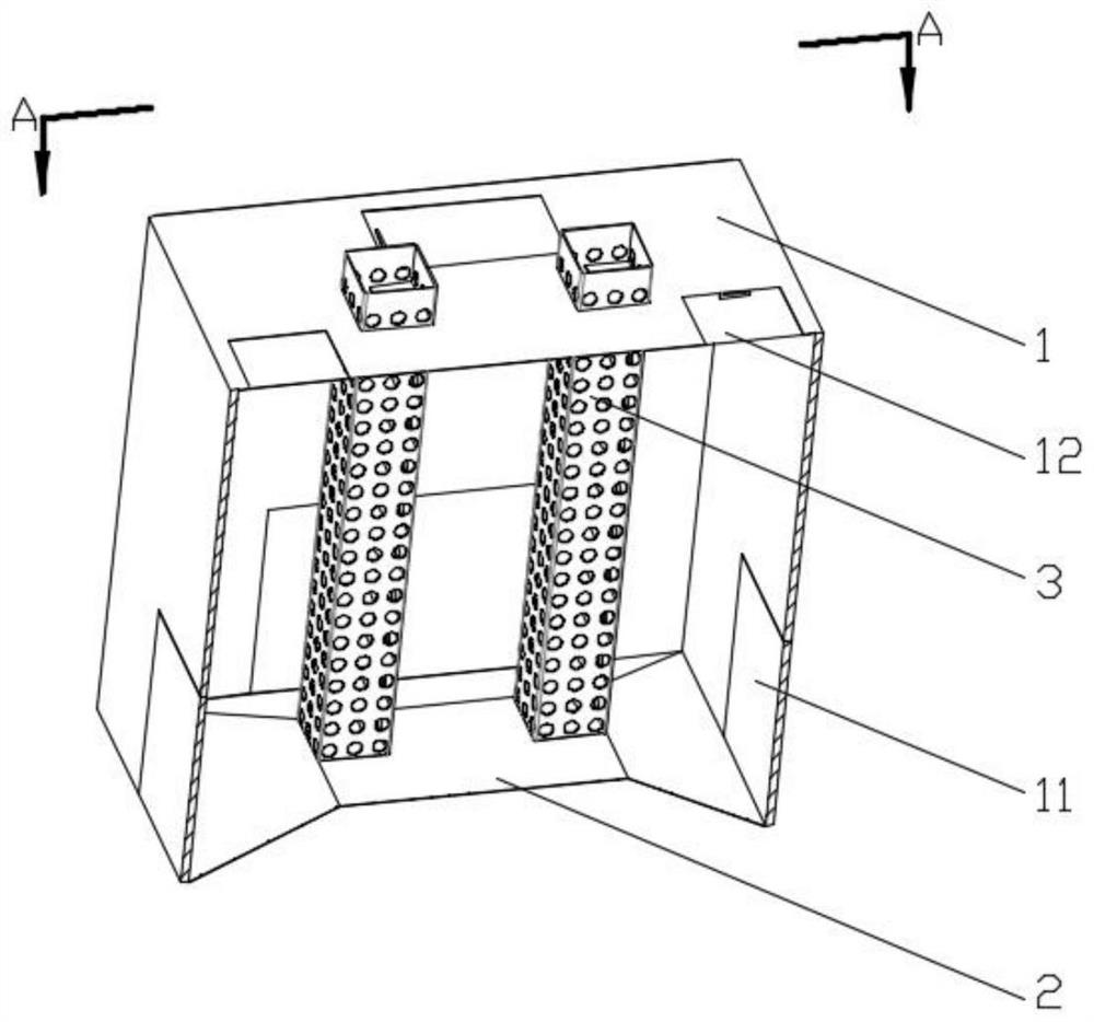
[0028] refer to Figure 1-7 Shown is a thermal energy recycling garbage dehydrator, a housing 1, a deflector 2 and four air guide cylinders 3, wherein the deflector 2 is a four-pyramid frustum deflector casing, and the four-pyramid frustum deflector casing is arranged on the casing 1, and the top of the truncated pyramid guide shell is provided with four smoke inlets 21 in an array. The four air guide tubes 3 are all arranged inside the shell 1, and the top of each air guide tube 3 runs through the shell 1, and the bottom end of each air guiding tube 3 is set correspondingly to a smoke port 21 respectively.

[0029] The side walls around the casing 1 are respectively provided with a discharge door 11, and each discharge door 11 is adjacent to the deflector 2; the top of the casing 1 is provided with 4 feed doors 12, and each feed door 12 Corresponding to a discharge gate 11 respectively.

[0030] In this embodiment, the four air guiding cylinders 3 are kept at a certain dist...


PUM


Abstract

The invention discloses a garbage dehydrator capable of recycling heat energy, and relates to the technical field of garbage treatment devices, the garbage dehydrator comprises a shell, a guide plate and a gas guide cylinder; the flow guide plate is arranged at the bottom end of the shell; and two ends of the air guide cylinder are respectively communicated with the top end of the shell and the flow guide plate. According to the device, heat energy in tail gas discharged by a thermal power plant can be recycled, dehydration of wet garbage such as fruit peels and leaves is accelerated, combustion power generation of the fruit peels and the leaves in follow-up work is facilitated, and the device is simple in structure, reasonable in arrangement, low in cost and high in practicability.

Description

technical field [0001] The invention relates to the technical field of garbage treatment devices, and more specifically relates to a thermal energy recycling garbage dehydrator. Background technique [0002] With the development of society, people continue to produce all kinds of garbage in their life and production. If they bury the garbage underground, some garbage will not rot after hundreds of years. If the garbage is discharged into the sea, it will easily cause marine pollution and endanger the ocean. Therefore, various countries are vigorously developing waste power plants. However, the high-temperature tail gas discharged from the waste incineration power plant in the prior art does not recycle the heat in the tail gas, thus causing a huge waste of energy, and before the waste is incinerated, the waste is mixed with some leaves, fruit peels, etc. Moisture in the garbage, thus reducing the efficiency of burning the garbage. [0003] Therefore, how to provide a waste...

Claims


Application Information

Patent Timeline
Patent Type & Authority Applications(China)
IPC IPC(8): F26B9/06F26B21/00F26B25/00F26B25/12
CPCF26B9/06F26B21/001F26B25/002F26B25/12
Inventor 黎炽荣
Owner 广东肇庆天盛泰景环保科技有限公司
Why Eureka
Try Eureka