Excavation-controllable foundation pit model test device and method

A model test device and foundation pit technology, applied in the direction of measuring devices, mechanical devices, mechanical measuring devices, etc., can solve the problems of model box size limitation, difficulty in accurately measuring the deformation of enclosure structures, etc., to achieve convenient simulation and avoid man-made Disturbing, easy-to-operate effects

Pending Publication Date: 2022-03-18
NINGBO METRO GRP
View PDF5 Cites 0 Cited by
  • Summary
  • Abstract
  • Description
  • Claims
  • Application Information

AI Technical Summary

Problems solved by technology

[0004] The deformation measurement of the enclosure structure in the model test is also a difficult point. Some scholars have pasted strain gauges on the enclosure structure, and calculated the deformation of the enclosure structure through strain transformation. However, this test method is limited by the temperature and the number of measuring points. It is difficult to accurately measure the actual deformation of the envelope
Some scholars have installed a dial indicator on the enclosure structure. Although the dial indicator can accurately measure the deformation of the enclosure structure, the dial indicator needs to be connected to the table base with a connecting rod. Due to the size limit of the model box, only Can monitor the displacement of individual parts of the enclosure structure

Method used


Image

  • Excavation-controllable foundation pit model test device and method
  • Excavation-controllable foundation pit model test device and method
  • Excavation-controllable foundation pit model test device and method

Examples


Embodiment 1

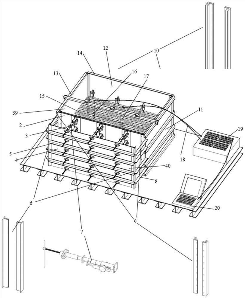
[0066] Embodiment 1 of the present application provides a controllable excavation pit model test device, including a model box outer frame 39, simulated soil 15, support baffle parts 40, support parts 7 and test instrument assemblies.

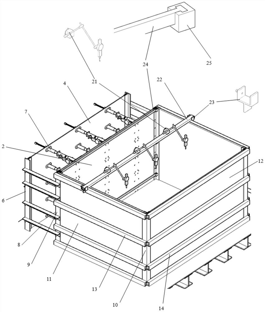
[0067] The model box outer frame 39 is composed of base 1, front column 9, rear column 10, enclosure baffle plate 2, plexiglass side panel 11, back panel 12, side panel reinforcement rib 13, back panel reinforcement rib 14, front Pull rod 24 forms. The base 1 is formed by welding 4 pieces of 2m×1.25m steel plates and 11 I-beams with a height of 10cm. The base 1 is used as a platform for the model test to ensure the stability of each part of the model test. The front column 9 is in order to connect the enclosure baffle 2 and the plexiglass side panel 11, so the front column 9 contains the slots of the enclosure baffle 2 and the plexiglass side panel 11, the front column is 1.1m high, and the section is as attached Figure 9 shown. In addition...

Embodiment 2

[0073] Embodiment 2 of the present application provides an assembly and test method of a controllable excavation pit model test device, the steps are as follows:

[0074] S1. Complete the construction of the base 1 with iron plates and I-beams. Weld support baffle column 6, front column 9 and rear column 10. Weld the side plate reinforcing ribs 13 and insert the plexiglass side plate 11. The front tie rod bearing 25 is welded on the top of the front column 9, and the two ends of the front tie rod 24 are inserted in the slot of the front tie rod bearing 25. Insert the back plate 12, and weld the back plate reinforcing ribs 14. Insert the support baffle 4 in the slot of the support baffle column 6, and weld the support baffle reinforcement rib 5. Insert the enclosure baffle 2 in the slot of the front column 9, install the supporting part steel backing plate 3 on the enclosure baffle 2, install the supporting part 7, install the side connecting rod 8 of the supporting baffle, ...


PUM

PropertyMeasurementUnit
diameteraaaaaaaaaa
thicknessaaaaaaaaaa
gauge factoraaaaaaaaaa

Abstract

The invention relates to an excavation-controllable foundation pit model test device which comprises a model box outer frame, simulated soil, a supporting baffle component, a supporting component and a test instrument assembly. The model box outer frame is composed of a front stand column, an enclosure baffle, organic glass side plates, a back plate and a front pull rod. The supporting baffle component is mainly composed of a supporting baffle, supporting baffle reinforcing ribs and supporting baffle stand columns. The supporting component is mainly composed of a rotating handle, a lead screw, a spring inner sleeve, a spring outer sleeve and a supporting component connecting end plate. The test instrument assembly comprises a top settlement reference rod, a top settlement dial indicator, a miniature soil pressure gauge, a miniature pore water pressure gauge, a signal acquisition instrument and a computer. The model device has the beneficial effects that the supporting part is arranged between the enclosure baffle and the supporting baffle, foundation pit excavation can be achieved through unloading of the supporting part, simulation of foundation pit excavation is facilitated, and manual disturbance during manual excavation is avoided.

Description

technical field [0001] The invention belongs to the field of foundation pit engineering, and in particular relates to a controllable excavation foundation pit model test device and method. Background technique [0002] Restricted by the site environment and construction conditions, many scholars have used model tests to study the deformation and internal forces of the enclosure structure, surrounding strata, and adjacent structures during the excavation process of different types of foundation pits. The model test of foundation pit excavation includes two steps, one is the excavation of the soil in the pit, and the other is the support erection of the enclosure structure. These two steps have a great influence on the results of the model test. Excavation of foundation pits is often carried out in layers and blocks. Due to the nonlinear mechanical properties of the soil and the excavation of the soil often requires manual excavation with a shovel. These two factors make the e...

Claims


Application Information

Patent Timeline
Patent Type & Authority Applications(China)
IPC IPC(8): G01C5/00G01B5/02G01B5/30G01L11/00
CPCG01C5/00G01B5/02G01B5/30G01L11/00
Inventor 陆幸周晔叶俊能郦亮叶荣华钱峰刘干斌
Owner NINGBO METRO GRP
Why Eureka
Try Eureka