Temperature detection of power switches using modulation of driver output impedance
A technology of power switch and output impedance, which is applied in output power conversion devices, thermometers and thermometers using electrical/magnetic components directly sensitive to heat, etc., can solve problems such as inaccuracy and delay in response
- Summary
- Abstract
- Description
- Claims
- Application Information
AI Technical Summary
Problems solved by technology
Method used
Image

Examples
example 1- 1
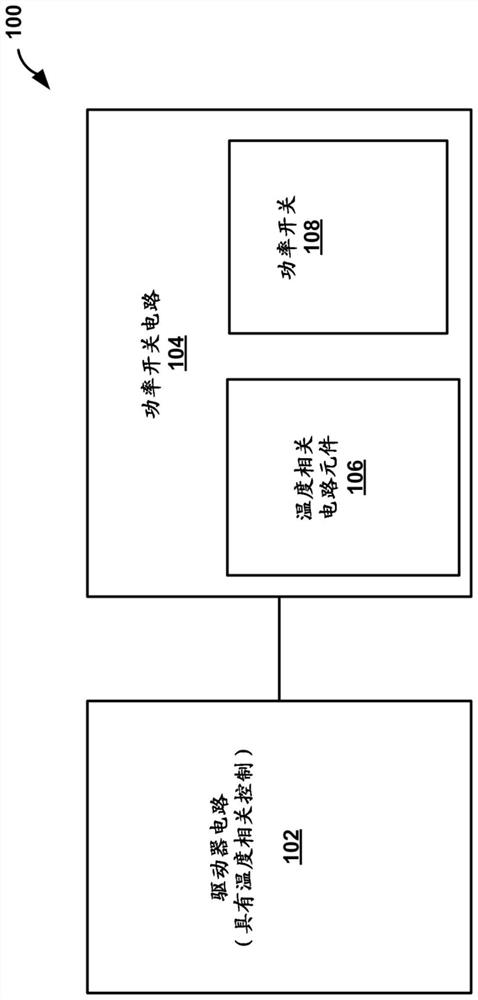
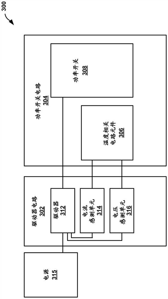
[0102] Example 1 - A circuit comprising a driver circuit configured to control a power switch circuit comprising a power switch and a temperature dependent circuit element electrically coupled to at least one node of the power switch : wherein the driver circuit is configured to deliver a modulated signal to a control node of the power switch to control on / off switching of the power switch, wherein the driver circuit is configured to implement a circuit related to the temperature element associated current measurement and voltage measurement, and controlling the power switch based at least in part on the current measurement and the voltage measurement, and wherein the current measurement and the voltage measurement are based on the Timing associated with on / off switching is performed.
[0103] EXAMPLE 2 The circuit of example 1, wherein the current measurement and the voltage measurement are performed when a voltage across the power switch is stable and the power switch is not...
example 27- 1
[0128] EXAMPLE 27 - A method of controlling a power switching circuit comprising a power switch and a temperature dependent circuit element electrically coupled to at least one node of the power switch, the method comprising: providing the A control node of a power switch delivers a modulated signal to control on / off switching of the power switch; performs a current measurement associated with the temperature dependent circuit element; performs a voltage measurement associated with the temperature dependent circuit element and controlling the power switch based at least in part on the current measurement and the voltage measurement.
[0129] Example 28 The method of example 27, further comprising performing the current measurement and the voltage measurement according to a timed sequence based on timing associated with the on / off switching of the power switch.
[0130] EXAMPLE 29 The method of examples 27 or 28, wherein controlling the power switch comprises controlling the po...
example 35- 1
[0136] Example 35 - A circuit arrangement comprising: a power switch circuit comprising a power switch and a temperature dependent circuit element electrically coupled to at least one node of the power switch; and a driver circuit configured to provide power to the power switch A control node of a switch delivers a modulated signal to control on / off switching of the power switch, wherein the driver circuit is configured to perform current and voltage measurements associated with the temperature dependent circuit element and based at least in part on The current measurement and the voltage measurement control the power switch, and wherein the current measurement and the voltage measurement are performed based on timing associated with the on / off switching of the power switch.
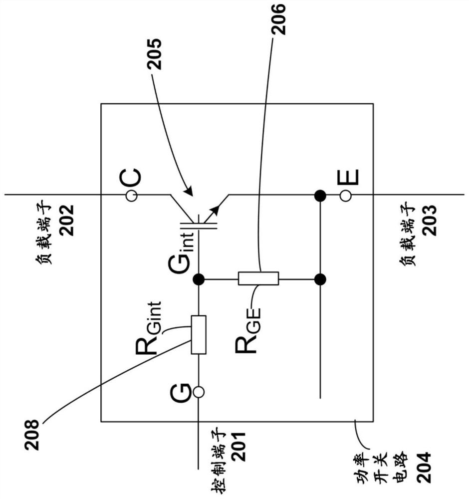
[0137] EXAMPLE 36 The circuit arrangement of Example 35, wherein the temperature dependent circuit element comprises a temperature dependent resistor.
[0138] EXAMPLE 37 The circuit arrangement of examp...
PUM
 Abstract
Description
Claims
Application Information
 - R&D Engineer
- R&D Manager
- IP Professional
- Industry Leading Data Capabilities
- Powerful AI technology
- Patent DNA Extraction
Browse by: Latest US Patents, China's latest patents, Technical Efficacy Thesaurus, Application Domain, Technology Topic.
© 2024 PatSnap. All rights reserved.Legal|Privacy policy|Modern Slavery Act Transparency Statement|Sitemap