Optical fiber exchange box for communication engineering construction

A communication engineering and switching box technology, which is applied in the field of optical fiber switching boxes for communication engineering construction, can solve the problems of insufficient buffering to protect internal components, difficulty in effectively guaranteeing safety, and fluctuations in internal components, so as to improve service life. , Avoid the danger of long-term high-altitude work, and prevent the effect of rainwater accumulation

Pending Publication Date: 2022-03-18
HEILONGJIANG UNIVERSITY OF SCIENCE AND TECHNOLOGY
View PDF0 Cites 2 Cited by
  • Summary
  • Abstract
  • Description
  • Claims
  • Application Information

AI Technical Summary

Problems solved by technology

[0003] Most of the original optical fiber switching boxes used in communication engineering construction are installed outdoors. The wind and the sun make the inside sometimes heat up, and sometimes the rain infiltrates, which greatly limits its service life, and the box body is impacted. There is not enough cushioning to protect the internal components, which leads to large fluctuations in the operation of the internal components, and the use effect is not good. In addition, the box is often installed at a certain height, and the original box is connected by a large number of bolts at the four ends. Effective fixing, this method is not only cumbersome to install, but also difficult to effectively guarantee safety during high-work operations

Method used


Image

  • Optical fiber exchange box for communication engineering construction
  • Optical fiber exchange box for communication engineering construction
  • Optical fiber exchange box for communication engineering construction

Examples


Embodiment

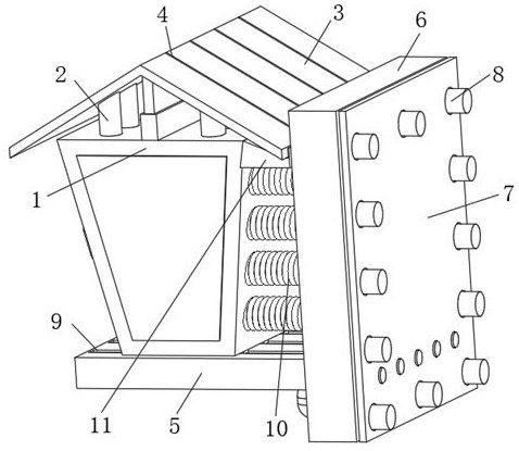
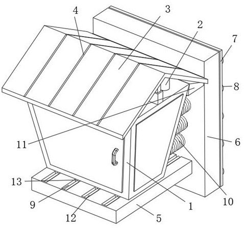
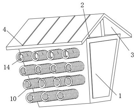
[0023] see Figure 1-6 , the present invention provides the following technical solutions: a fiber exchange box for communication engineering construction, including a main body 1, two ends of the main body 1 are provided with cooling holes for heat dissipation, and the lower end of the main body 1 is provided with a sliding block 13 connected to the connecting base plate 5 , the connecting bottom plate 5 is provided with a sliding groove 9 for the limiting sliding action of the main body 1, the other end of the connecting bottom plate 5 is fixedly connected with the side connecting plate 6 through bolts, and the connection between the connecting bottom plate 5 and the side standing connecting plate 6 is provided with two The motor used for transmission, the side connecting plate 6 is provided with evenly distributed transmission rods 8, and a rubber pad 7 for increasing the compactness of the connection is also provided. The other end of the side standing connecting plate 6 is...


PUM


Abstract

The invention belongs to the technical field of optical fiber exchange boxes, and particularly relates to an optical fiber exchange box for communication engineering construction, which comprises a main body, heat dissipation holes for heat dissipation are formed in two ends of the main body, the lower end of the main body is connected with a connecting bottom plate through a sliding block, and a sliding groove for limiting and sliding the main body is formed in the connecting bottom plate. Through the arrangement of the side vertical connecting plate, the side vertical connecting plate is driven by a motor at the lower end, so that the side vertical connecting plate is fixed to a wall surface in a threaded mode through a transmission rod, the effect of conveniently installing and fixing the main body is achieved, and the danger of long-time high-altitude operation is effectively avoided; and through arrangement of a connecting bottom plate, the connecting bottom plate drives a transmission lead screw to rotate through a motor at the lower end, so that the position of the main body is adjusted, the position of the main body is conveniently adjusted according to weather conditions, the information transmissibility of the main body is improved, and meanwhile, the flexibility of the main body is improved.

Description

technical field [0001] The invention belongs to the technical field of optical fiber switching boxes, and in particular relates to an optical fiber switching box for communication engineering construction. Background technique [0002] Communication engineering (also known as: information engineering, telecommunication engineering. Formerly known as: long-distance communication engineering, weak current engineering) communication engineering is an important branch of electronic engineering and one of the basic disciplines; this discipline focuses on information transmission in the communication process and signal processing, the principle and application; communication engineering research is to transmit information through electrical pulses in the form of electromagnetic waves, sound waves or light waves, from the sending end (source) to one or more receiving ends (sink); the receiving end Whether the information can be correctly identified depends on the loss in transmissi...

Claims


Application Information

Patent Timeline
IPC IPC(8): G02B6/44F16M11/04F16M11/18F16M13/02F16F15/067H02J7/35H02S20/23
CPCG02B6/4446F16M11/04F16M11/043F16M11/18F16M13/02F16F15/067H02J7/35H02S20/23Y02E10/50Y02B10/10
Inventor 陈丽娟刘鑫张小清
Owner HEILONGJIANG UNIVERSITY OF SCIENCE AND TECHNOLOGY
Why Eureka
Try Eureka