
Control circuit, control method, driving circuit and lighting device

A control method and technology of control circuits, applied in the sequence/logic controller in the direction of program control, electrical program control, electrical components, etc., can solve the problems of inconsistent electrical characteristics, difficult calculation, high cost, etc.

Pending Publication Date: 2022-03-18
张继
View PDF0 Cites 0 Cited by
  • Summary
  • Abstract
  • Description
  • Claims
  • Application Information

AI Technical Summary

Problems solved by technology

Furthermore, it is known that the rectified voltage of the power grid spans the interval of (0, maximum value), and the number of LED voltage groups that are turned on is the same as the number of current sources that control the conduction current. If higher efficiency is to be satisfied, A larger number of segments is required, which complicates the circuit structure and leads to higher cost
[0008] Furthermore, because the electrical characteristics of LEDs in different LED groups may also be inconsistent, the conduction voltage drop or conduction threshold of LEDs is not completely constant, but changes with changes in operating temperature, operating current, etc., so This is difficult to calculate. The characteristics between the voltage of the LED string and the current of the LED lack a simple, accurate, and quantitative correspondence. In order to ensure that the power supply voltage before and after switching between different LED groups can be sufficient to drive the LED string, it is often necessary When the power supply voltage is greater than the conduction voltage drop of the LED string and there is enough margin, the switching action is performed to switch different LED strings into or out of the power supply circuit. This switching with sufficient margin will cause Efficiency is reduced, and switching is usually instantaneous, which also brings large electromagnetic interference (EMI)

Method used


Image

  • Control circuit, control method, driving circuit and lighting device
  • Control circuit, control method, driving circuit and lighting device
  • Control circuit, control method, driving circuit and lighting device

Examples


Embodiment Construction

[0365] Exemplary embodiments of the present disclosure will be described in more detail below with reference to the accompanying drawings. Although exemplary embodiments of the present disclosure are shown in the drawings, it should be understood that the present disclosure may be embodied in various forms and should not be limited by the embodiments set forth herein. Rather, these embodiments are provided for more thorough understanding of the present disclosure and to fully convey the scope of the present disclosure to those skilled in the art.

[0366] The inventor found through research that: LED arrays in the circuits of some technical solutions are generally removed from the circuit or connected into the circuit according to the voltage of the power supply by selectively turning on the controllable switches coupled with these LED arrays. This kind of control of the controllable switch is generally implemented by the control unit, and the control unit cannot know the prec...


PUM


Abstract

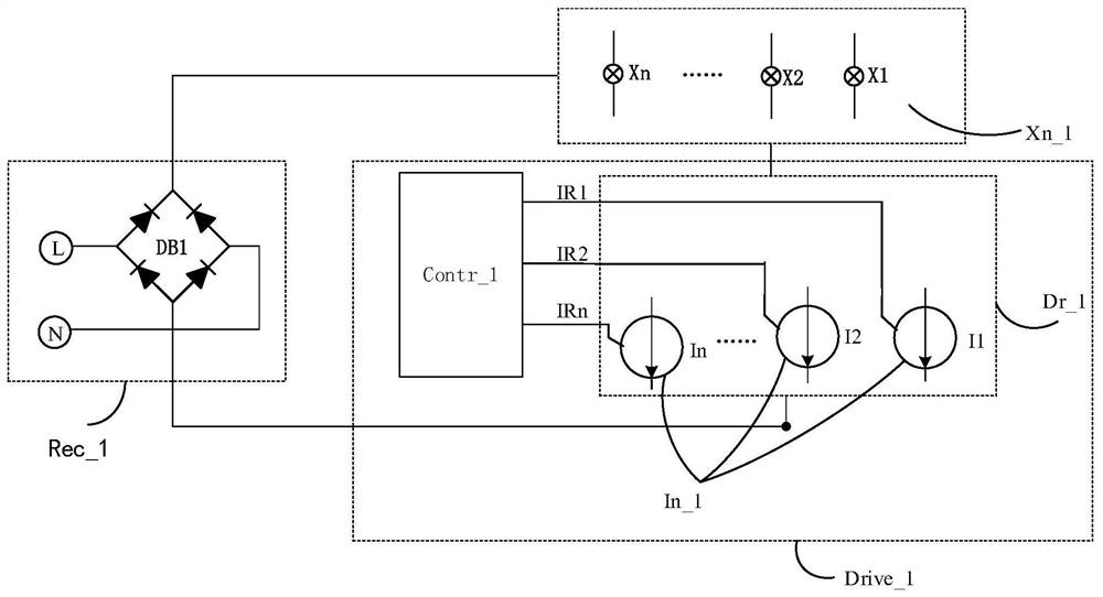
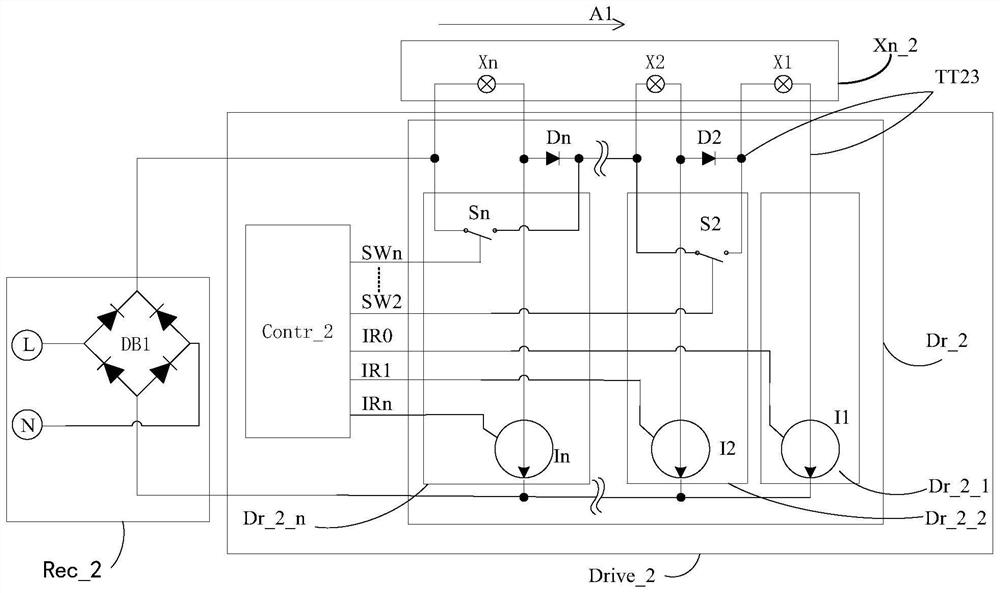
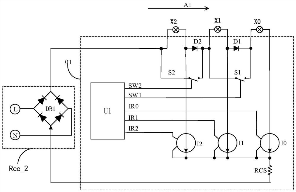
The invention discloses a control circuit, a control method, a driving circuit and a lighting device, and relates to the field of circuit load control. The control circuit includes: a control unit, (n-1) switching units connected in series; the negative polarity end of the first controlled current source in the n controlled current sources is connected to a common ground terminal, and the positive polarity ends of the other (n-1) controlled current sources are correspondingly connected to the negative electrodes of the (n-1) switch units through one one-way switch respectively; the one-way switch is configured to block current between the corresponding switch unit and the controlled current source; the negative polarity ends of the (n-1) controlled current sources are connected to the common ground terminal; the control ends of the n controlled current sources and the control ends of the (n-1) switch units are respectively connected to the control unit; wherein n is an integer and is greater than or equal to 2. Therefore, the continuity / smoothness in the switching process between different LED array combinations is enhanced.

Description

technical field [0001] The present application relates to the technical field of drive circuits, in particular to the technical field of control circuits for solid-state light emitters, and relates to a control circuit, a control method, a drive circuit and a lighting device. Background technique [0002] Light-emitting diode (LED) refers to a semiconductor element that can reflect light of various colors through a PN diode light source composed of a compound semiconductor. This light-emitting element has the advantages of long life, miniaturization and weight reduction, low-voltage driving, and the like. In addition, this light-emitting diode is highly resistant to shock and vibration, and does not require warm-up time and complicated driving. LEDs can be packed in substrates or LED frames in various forms, so they can be patterned into various Application, applied to backlight unit (backlight unit) or various lighting devices, etc. [0003] Use light-emitting diodes to p...

Claims


Application Information

Patent Timeline
IPC IPC(8): G05B19/04H05B45/30
CPCG05B19/04H05B45/30
Inventor 张继
Owner 张继
Learn More