High-speed embedded permanent magnet synchronous motor rotor structure

A permanent magnet synchronous motor, rotor structure technology, applied in the magnetic circuit shape/style/structure, magnetic circuit rotating parts, magnetic circuit and other directions, to achieve high tensile strength, reduced leakage magnetic flux, and improved magnetoresistance effect Effect

Pending Publication Date: 2022-03-18
SHAANXI AVIATION ELECTRICAL
View PDF0 Cites 0 Cited by
  • Summary
  • Abstract
  • Description
  • Claims
  • Application Information

AI Technical Summary

Problems solved by technology

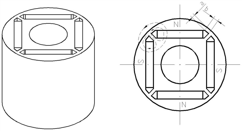
[0003] Specific as figure 1 As shown, in the permanent magnet motor in the form of an inner rotor, the magnetic steel provides the excitation magnetic potential, and the main magnetic flux of the magnetic field enters the stator through the air gap of the motor to form the main magnetic flux, but a part of the magnetic flux forms a loop inside the rotor, forming a leakage. magnetic flux

Method used


Image

  • High-speed embedded permanent magnet synchronous motor rotor structure
  • High-speed embedded permanent magnet synchronous motor rotor structure
  • High-speed embedded permanent magnet synchronous motor rotor structure

Examples


Embodiment Construction

[0028] Embodiments of the present invention are described in detail below, examples of which are shown in the drawings, wherein the same or similar reference numerals designate the same or similar elements or elements having the same or similar functions throughout. The embodiments described below by referring to the figures are exemplary and are intended to explain the present invention and should not be construed as limiting the present invention.

[0029] In describing the present invention, it should be understood that the terms "center", "longitudinal", "transverse", "length", "width", "thickness", "upper", "lower", "front", " Orientation indicated by rear, left, right, vertical, horizontal, top, bottom, inside, outside, clockwise, counterclockwise, etc. The positional relationship is based on the orientation or positional relationship shown in the drawings, which is only for the convenience of describing the present invention and simplifying the description, rather than ...


PUM


Abstract

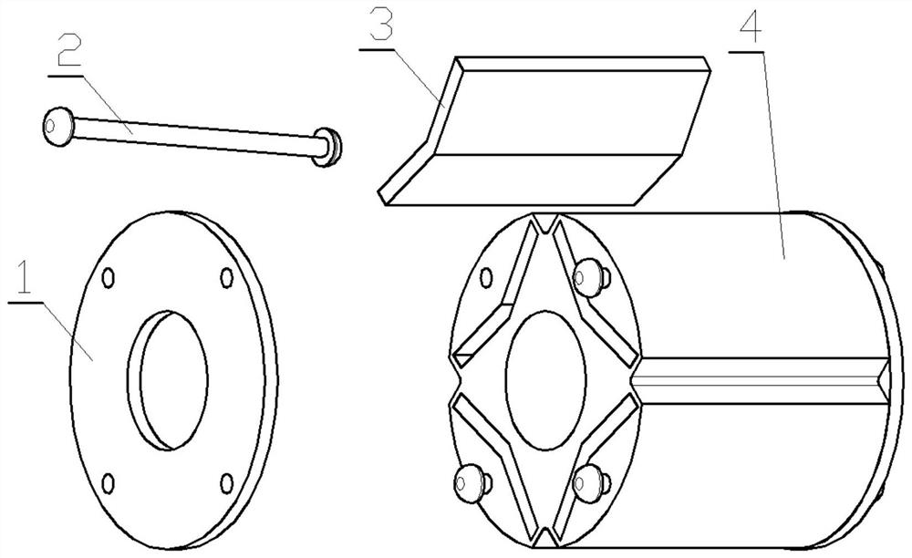
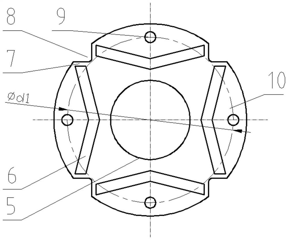
The invention provides a rotor structure of a high-speed embedded permanent magnet synchronous motor. The rotor structure is of a cylindrical structure which is formed by combining reinforcing plates, supporting rods, magnetic steel and rotor punching sheets and provided with axial right-angle grooves in the outer surface. The rotor punching sheet is made of a soft magnetic material, the center is provided with a punching sheet inner circle matched with a motor shaft, and the periphery is provided with punching sheet inner grooves for embedding magnetic steel; the two ends of the punching sheet inner groove are provided with a magnetic bridge used for supporting and a magnetic isolation groove used for magnetic isolation. Punching sheet pole shoes are arranged on the outer sides of the punching sheet inner grooves, and punching sheet fixing holes for embedding the supporting rods are formed in the punching sheet pole shoes; the magnetic bridge is designed in a direction parallel to the stress of the magnetic steel and the punching sheet pole shoe; the reinforcing plate is made of a non-magnetic material and is provided with a reinforcing plate inner circle matched with the motor shaft and a fixing hole matched with the supporting rod; after a plurality of rotor punching sheets are coaxially combined and superposed, magnetic steel is embedded in the inner grooves of the punching sheets, a reinforcing plate is arranged at the end part of the superposed combination of the rotor punching sheets, and the rotor punching sheets and the reinforcing plate are fixedly connected through a supporting rod.

Description

technical field [0001] The invention relates to the technical field of permanent magnet synchronous motors, in particular to a high-speed embedded permanent magnet synchronous motor rotor structure. Background technique [0002] The rotor structure of permanent magnet synchronous motor is generally divided into surface mount type and embedded type according to the position of the permanent magnet on the rotor. It is hollow inside and embedded with magnetic steel. [0003] Specific as figure 1 As shown, in the permanent magnet motor in the form of an inner rotor, the magnetic steel provides the excitation magnetic potential, and the main magnetic flux of the magnetic field enters the stator through the air gap of the motor to form the main magnetic flux, but a part of the magnetic flux forms a loop inside the rotor, forming a leakage. flux. The magnitude of the leakage flux is determined by the width of the magnetic bridge formed by the dimensions a and b, where the smalle...

Claims


Application Information

Patent Timeline
Patent Type & Authority Applications(China)
IPC IPC(8): H02K1/276H02K1/02H02K1/28H02K1/22G06F30/17G06F30/20
CPCH02K1/276H02K1/02H02K1/28H02K1/22G06F30/17G06F30/20H02K2213/03
Inventor 赵群弼王培路武思文
Owner SHAANXI AVIATION ELECTRICAL
Why Eureka
Try Eureka