
Pump room pressure flow water attack automatic control system and control method

An automatic control system and pressure technology, applied in the pipeline system, pipes/pipe joints/fittings, mechanical equipment, etc., can solve the problems of poor energy saving and consumption reduction, poor water hammer control, and unknown water pump 001 output flow diversion flow And other issues

Pending Publication Date: 2022-03-22
KC VAL SHANGHAI
View PDF0 Cites 0 Cited by
  • Summary
  • Abstract
  • Description
  • Claims
  • Application Information

AI Technical Summary

Problems solved by technology

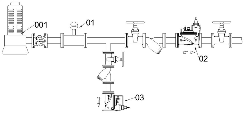
[0004] If the flowmeter 01 is installed in front of the relief valve 03 (see figure 1 ), then the flowmeter 01 can only measure the output flow of the water pump 001, and the system cannot know the shunt flow of the pressure relief valve 03 and the actual user flow through the pressure relief valve 02; and if the flowmeter is installed on the pressure relief valve 03 backend (see figure 2 and image 3 ), the system can only measure the actual user flow through the pressure reducing valve 02, but does not know the output flow of the water pump 001 and the shunt flow of the pressure relief valve 03
[0005] At present, the pipe network system often uses electric contact pressure gauges and control boxes to control the start-stop and input power of the water pump. However, the accuracy deviation of the electric contact pressure gauge itself and the poor response sensitivity lead to the adjustment of the input frequency and input power of the water pump. There is a large delay phenomenon, the effect of energy saving and consumption reduction is poor, and the control effect of water hammer is poor. At the same time, the real-time online display of the inlet and outlet pressure and flow of the pressure reducing valve and pressure relief valve is not accurate.
[0006] At the same time, the above problems also lead to an increase in the probability of water hammer inside the water pipes of the pump room, especially when the pipeline in the pump room is used for the first time or the pipeline at the user end starts the pump to supply water, and the water pressure at the outlet of the pressure reducing valve fluctuates Changes, the pressure at the inlet end of the pressure reducing valve changes instantaneously, when the pump is stopped normally or when the pump is stopped due to a sudden power failure, etc.

Method used


Image

  • Pump room pressure flow water attack automatic control system and control method
  • Pump room pressure flow water attack automatic control system and control method
  • Pump room pressure flow water attack automatic control system and control method

Examples


Embodiment Construction

[0052] The following description serves to disclose the present invention to enable those skilled in the art to carry out the present invention. The preferred embodiments described below are only examples, and those skilled in the art can devise other obvious variations. The basic principles of the present invention defined in the following description can be applied to other embodiments, variations, improvements, equivalents and other technical solutions without departing from the spirit and scope of the present invention.

[0053] Those skilled in the art should understand that in the disclosure of the specification, the terms "vertical", "transverse", "upper", "lower", "front", "rear", "left", "right", "vertical The orientations or positional relationships indicated by "straight", "horizontal", "top", "bottom", "inner", "outer", etc. are based on the orientation or positional relationships shown in the drawings, which are only for the convenience of describing the present i...


PUM


Abstract

The invention discloses an automatic control system and method for pressure, flow and water attack of a pump room. The automatic control system comprises two electro-hydraulic valves, a plurality of pressure sensors and a controller. The electro-hydraulic valves are respectively implemented as a pressure release valve and a pressure reducing valve, the pressure release valve is arranged on a pressure release branch pipeline of the pipeline, and the pressure reducing valve is arranged on the pressure reducing branch pipeline; the electro-hydraulic valve comprises a main valve, a first control valve and a second control valve, the main valve is provided with a valve cavity, the first control valve is arranged on a first guide pipe, communicated with the valve cavity, of the inlet end of the main valve, and the second control valve is arranged on a second guide pipe, communicated with the valve cavity, of the outlet end of the main valve; the pressure sensors are arranged at the inlet ends and the outlet ends of the two main valves and the preset positions of the pipeline respectively. The first control valve, the second control valve and the pressure sensor are all in electric signal connection with the controller. The control system can save energy, reduce consumption and reduce water hammers.

Description

technical field [0001] The invention relates to the technical field of pump room pipeline control, in particular to a pump room pressure flow water hammer automatic control system and control method. Background technique [0002] In the general pipeline system, the traditional pressure control valve is a pressure reducing valve or a pressure relief valve, whether it is a direct acting pressure reducing valve or a pressure relief valve, a pilot type pressure reducing valve or a pressure relief valve, or a diaphragm Neither the pressure reducing valve nor the pressure relief valve has the function of collecting and displaying the instantaneous flow rate or the accumulated flow rate. [0003] At present, the conventional method of use is a separate pipeline flow meter 01 + a separate pressure reducing valve 02 (see figure 1 and figure 2 ), or an integral flow meter pressure reducing valve (see image 3 ). [0004] If the flowmeter 01 is installed in front of the relief val...

Claims


Application Information

Patent Timeline
IPC IPC(8): F17D1/14F17D3/01F16L55/02
CPCF17D1/14F17D3/01F16L55/02
Inventor 蒲昌烈章莹
Owner KC VAL SHANGHAI
Learn More