Water meter

A technology for water meters and dials, which is applied to measuring devices, instruments, and liquid/fluid solid measurements, etc. It can solve the problems of hindering reading readings, difficult and laborious operation, etc., and achieve the effect of convenient, simple and labor-saving operation of reading table readings

Inactive Publication Date: 2022-03-22
沛县科鲁新能源技术服务中心
View PDF1 Cites 3 Cited by
  • Summary
  • Abstract
  • Description
  • Claims
  • Application Information

AI Technical Summary

Problems solved by technology

[0004] The purpose of the present invention is to provide a water meter to solve the problem mentioned in the background art that because the sealing glass of the dial is easy to accumulate sand and condense water droplets, blocking the normal viewing and reading, requiring personnel to clean it manually in a deep pit, and the operation is difficult and laborious. The problem

Method used


Image

  • Water meter
  • Water meter
  • Water meter

Examples


Embodiment 1

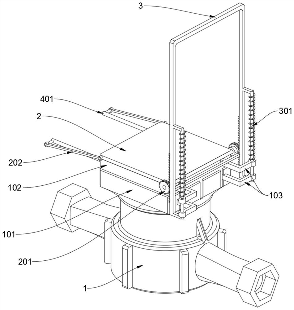
[0022] see Figure 1 to Figure 5 and Figure 7 , Figure 8 , Embodiment 1 provided by the present invention: a water meter, including a water meter body 1; the water meter body 1 includes a dial 101 and a surrounding frame 102, the water meter body 1 has a circular structure as a whole, and a square dial 101 is arranged on its top. A surrounding frame 102 is welded upwards on the top of the dial 101, and a square watch cover 2 is rotated on the top opening of the surrounding frame 102; It is convenient for the sponge strip 402 to scrape out the accumulated sand, gravel and soil inside the enclosure 102, avoiding excessive accumulation of sand, gravel and soil inside the enclosure 102, and saving the trouble of additional manual effort to clean the sand, gravel and soil; the water meter body 1 also includes L-shaped positioning rod 103, four L-shaped positioning rods 103 are symmetrically welded on the rear end shell wall of the dial 101, and a driving mechanism 3 runs throug...

Embodiment 2

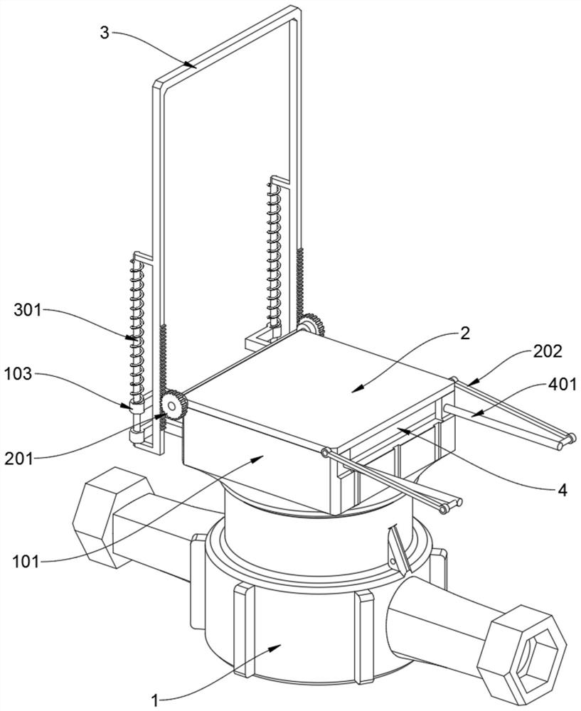
[0026] see Figure 6 , Embodiment 2 provided by the present invention: a water meter, including the tail ends of the two connecting rods 202 corresponding to the tail end sections of the two position limiting shafts 401 are rotatably connected together, the two connecting rods 202 and the two position limiting shafts 401 Together with the cover 2, a crank slider mechanism is formed. Through this mechanism, when the cover 2 is flipped open and closed, it can be linked and pushed to drive the brush plate 4 to be wiped back and forth, which saves additional manual effort to drive the brush plate 4. The hassle of cleaning the cover glass.

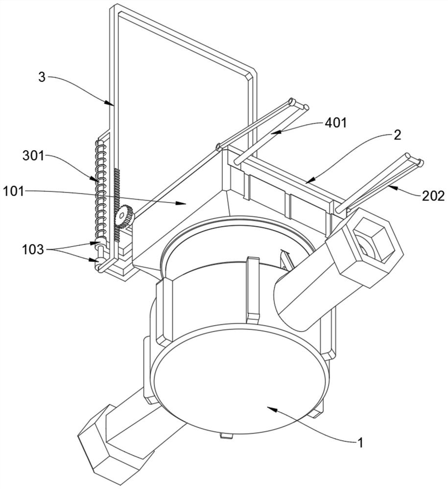
[0027] Working principle: the driving mechanism 3 can slide up and down to mesh and drive the two driven gears 201 to rotate forward and backward to control the switch of the meter cover 2, and the supporting length of the driving mechanism 3 is twice the length of the water meter body 1, which is higher depending on the driving mechanism 3 Su...


PUM


Abstract

The invention discloses a water meter, relates to the technical field of water meters, and solves the problems that according to an existing household water meter, due to the fact that sandy soil is easily accumulated on sealing glass of a dial plate and water drops are condensed, normal reading checking is obstructed by shielding, manual cleaning by personnel in a deep pit is needed, and operation is difficult and strenuous. A water meter comprises a water meter body. The water meter body comprises a dial plate and a surrounding frame, the whole water meter body is of a circular structure, the square dial plate is arranged at the top of the water meter body, the surrounding frame is upwards welded to the top end of the dial plate, and a square meter cover rotationally covers an opening in the top end of the surrounding frame; the two vertical positioning shafts are each sleeved with a spring, and the two rows of tooth pieces on the lower half sections of the two driving mechanisms are correspondingly in meshing transmission with the two driven gears. The long-strip-shaped grooves in the enclosure frame can be convenient for the sponge strips to scrape out gravel and mud accumulated in the enclosure frame, so that excessive gravel and mud are prevented from being accumulated in the enclosure frame, and the trouble of additionally manually applying force to clean the gravel and mud is saved.

Description

technical field [0001] The invention relates to the technical field of water meters, in particular to a water meter. Background technique [0002] A household water meter is an instrument for measuring the flow of tap water. It is the main link between a modern water supply system and an individual family. It is widely used. For example, the patent No. CN201010510462.X discloses a water meter, including a base meter. The base meter is provided with an impeller shaft assembly, and one end of the impeller shaft assembly is provided with a magnetic ring and protrudes outside the casing of the base meter. The base meter is provided with a casing, and a sensor assembly and a display assembly are arranged inside the casing. The data output end of the sensor assembly is connected to the data input end of the display assembly for data transmission, and the magnetic ring in the sensor assembly is magnetically coupled with the magnetic ring of the impeller shaft assembly. This kind o...

Claims


Application Information

Patent Timeline
Patent Type & Authority Applications(China)
IPC IPC(8): G01F15/12G01F15/00
CPCG01F15/12G01F15/00
Inventor 高明
Owner 沛县科鲁新能源技术服务中心
Why Eureka
Try Eureka