
Low-profile dielectric antenna

A dielectric antenna, low-profile technology, applied in the field of low-profile dielectric antennas, can solve the problems of dielectric antenna power consumption or size and bandwidth that are difficult to meet the development needs of 5G mobile communication technology, narrow antenna bandwidth, high loss, etc., and achieve low prices. , the effect of expanding bandwidth and reducing radiation loss

Pending Publication Date: 2022-03-22
XI AN JIAOTONG UNIV
View PDF7 Cites 0 Cited by
  • Summary
  • Abstract
  • Description
  • Claims
  • Application Information

AI Technical Summary

Problems solved by technology

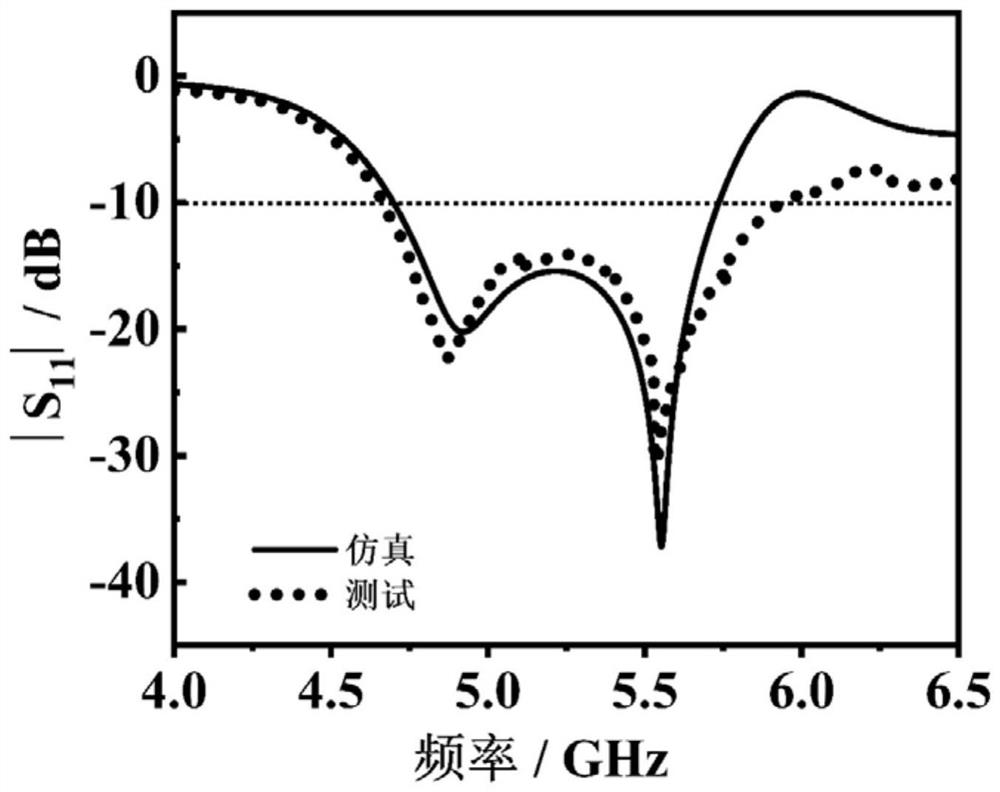
However, most of the existing dielectric antennas currently use high-loss dielectric materials, and the bandwidth of the antenna is often relatively narrow, which makes it difficult to meet the development requirements of 5G mobile communication technology regardless of the power consumption, size and bandwidth of the dielectric antenna.

Method used


Image

  • Low-profile dielectric antenna
  • Low-profile dielectric antenna
  • Low-profile dielectric antenna

Examples


Embodiment Construction

[0024] In order to enable those skilled in the art to better understand the solutions of the present invention, the following will clearly and completely describe the technical solutions in the embodiments of the present invention in conjunction with the drawings in the embodiments of the present invention. Obviously, the described embodiments are only The embodiments are a part of the present invention, not all embodiments, and are not intended to limit the scope of the present invention. Also, in the following description, descriptions of well-known structures and techniques are omitted to avoid unnecessarily obscuring the concepts disclosed in the present invention. Based on the embodiments of the present invention, all other embodiments obtained by persons of ordinary skill in the art without making creative efforts shall fall within the protection scope of the present invention.

[0025] The schematic diagrams of the structures according to the disclosed embodiments of th...


PUM

PropertyMeasurementUnit
quality factoraaaaaaaaaa
resonant frequency temperature coefficientaaaaaaaaaa
thicknessaaaaaaaaaa

Abstract

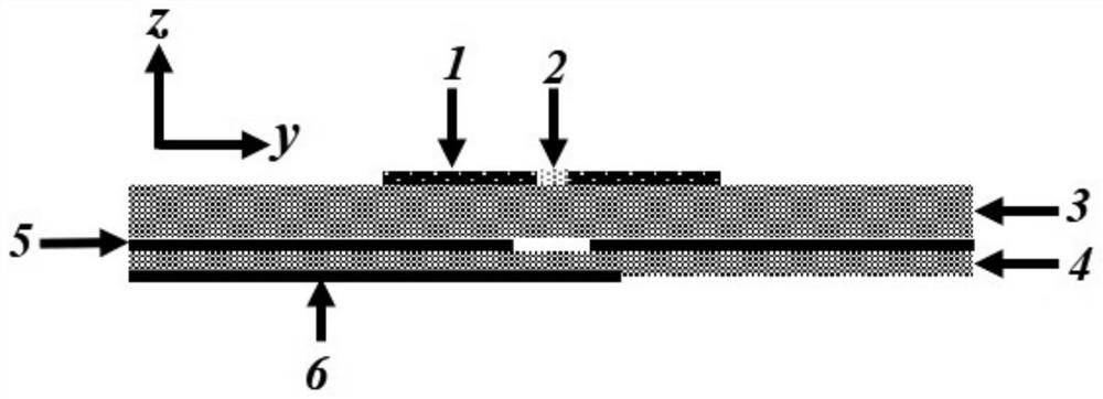
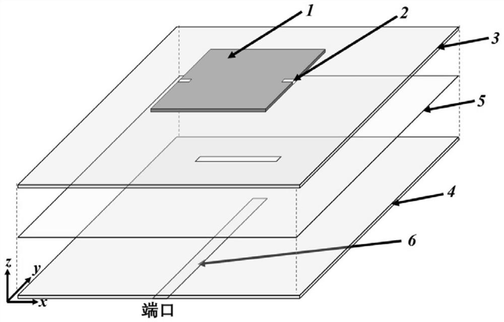
The low-profile dielectric antenna comprises a low-profile radiation patch structure, a middle-layer dielectric substrate and a bottom-layer dielectric substrate which are sequentially arranged from top to bottom, gap structures are arranged on the two opposite end faces of the low-profile radiation patch structure, silver coatings are arranged in the gap structures, and the silver coatings are arranged on the middle-layer dielectric substrate and the bottom-layer dielectric substrate. A metal bottom plate plane layer is arranged between the middle-layer dielectric substrate and the bottom-layer dielectric substrate, a linear coupling gap is formed in the middle of the metal bottom plate plane layer, a microstrip feeder line structure is arranged at the bottom of the bottom-layer dielectric substrate, the metal bottom plate plane layer and the microstrip feeder line structure form a feed structure, and the metal bottom plate plane layer is connected with the microstrip feeder line structure. The antenna has the characteristics of miniaturization, low power consumption and temperature stability.

Description

technical field [0001] The invention belongs to the technical field of antennas and relates to a low-profile dielectric antenna. Background technique [0002] In recent years, with the rapid development of fifth-generation (5G) mobile communication technology, 5G technology has now become the focus of a new round of technological competition in the global communication industry. This prompts the development of new passive microwave devices with high integration, high temperature stability and ultra-low power consumption to be paid more and more attention. Among them, one of the passive devices that promotes the development of 5G technology is the microwave antenna, which plays an important role in the terminal of the communication system. Therefore, in order to improve the performance of the antenna and reduce the size of the antenna, it is of great research and application value to design a high-performance dielectric material and a new antenna structure, which can obtain ...

Claims


Application Information

Patent Timeline
Patent Type & Authority Applications(China)
IPC IPC(8): H01Q1/38H01Q1/50H01Q13/10
CPCH01Q13/10H01Q1/38H01Q1/50
Inventor 周迪杜超吴芳芳李睿韬李达王威许昊鲍子妍
Owner XI AN JIAOTONG UNIV
Learn More