Illumination and positioning control system and method based on UWB intelligent lamp

A technology of positioning control and lamps, which is applied in the transmission system, energy-saving control technology, electrical components, etc., can solve the problems of difficult maintenance, chaotic management of lighting smart lighting lamps, low positioning accuracy, etc., and achieve the effect of preventing accidents

Active Publication Date: 2022-03-22
SHANDONG HUADING WEIYE ENERGY TECH
View PDF5 Cites 0 Cited by
  • Summary
  • Abstract
  • Description
  • Claims
  • Application Information

AI Technical Summary

Problems solved by technology

[0003] Most of the lighting in the working areas of high-risk industries currently uses traditional metal halide or sodium lamps with high energy consumption, low efficiency, short life, and difficult maintenance, which cannot respond to the national call for energy conservation and emission reduction
Due to the frequent flow of personnel and complex terrain during industrial and mining operations in high-risk industries such as mines and petrochemicals, there are high requirements for lighting and positioning technology and monitoring system software. Currently, technologies such as ZigBee, BLE, and RFID commonly used in the market are commonly used in lighting. Smart lighting fixtures have problems such as chaotic management, prolonged time, small coverage, low positioning accuracy, and small communication capacity, which cannot meet the basic operating environment requirements of safety, high efficiency, and high-quality lighting and positioning in the high-risk energy industry.

Method used


Image

  • Illumination and positioning control system and method based on UWB intelligent lamp
  • Illumination and positioning control system and method based on UWB intelligent lamp
  • Illumination and positioning control system and method based on UWB intelligent lamp

Examples


Embodiment 1

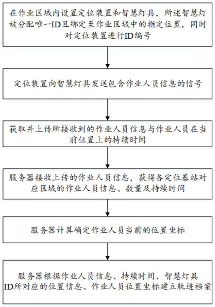
[0077] A method for positioning control of operators based on UWB technology, referring to image 3 , including the following steps:

[0078] Step S1. Set up multiple smart lamps in the work area, and the operator carries a positioning device. The smart lamps are assigned a unique ID and bound to a designated location in the work area, and at the same time ID number the positioning device;

[0079] Step S2. The positioning device sends a signal containing operator information to the smart lamp;

[0080] Step S3. The smart lamp acquires and uploads the received operator information and the duration of the operator at the current location;

[0081] Step S4. The server receives the operator information uploaded by the transmission module, and obtains the operator information and number in the corresponding area of ​​each smart lamp;

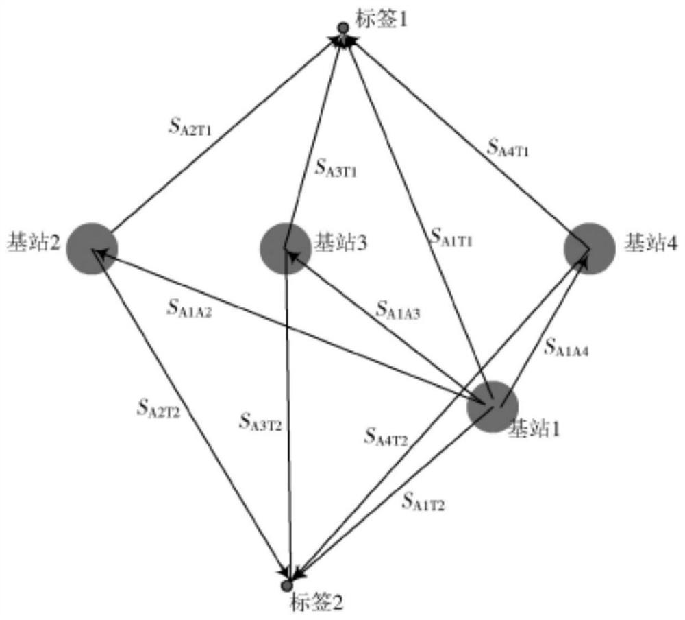
[0082] Step S5. The server calculates and determines the current position coordinates of the operator;

[0083] Step S6. The server creates a tr...

Embodiment 2

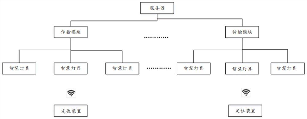
[0129] The invention also discloses an operator positioning control system based on UWB technology, referring to figure 1 , including a positioning device, a plurality of smart lamps, a server, and a plurality of transmission modules; the transmission module is connected and communicates with the smart lamps and servers; the smart lamp is connected to the positioning device in communication.

[0130] The smart lamp is assigned a unique ID and bound to a designated location in the operating area, and is used to receive a signal from a positioning device containing operator information, and combine the received operator information with the operator's current location. The duration is uploaded to the server; the smart lamp is also used to respond to the approach or distance of the operator to realize turning on or off and brightness adjustment; the smart lamp is also used to upload its operating status data to the server and receive the control sent by the server instruction.

...

Embodiment 3

[0138] The difference from other embodiments is that the smart lighting fixture also includes an electrical parameter acquisition module, the electrical parameter acquisition module is connected to the power supply module and the processor, and the electrical parameter acquisition module is used to obtain relevant operating state data of the lamp and Upload the operation status data to the server through the temperature sensor, the operation status data includes but not limited to voltage, current, power; The battery or supercapacitor in the lamp power module supplies power to itself. During the short-term (second-level) discharge process of the battery or supercapacitor, the smart lamp notifies the processor (sends information 3-5 times each time), and the server actively reports to the monitoring platform. And notify the operation and maintenance personnel by SMS to avoid the trouble caused by many smart lamps directly reporting to the monitoring platform. The operation and m...


PUM


Abstract

The invention discloses an illumination and positioning control system based on a UWB intelligent lamp, and the system comprises a positioning device which transmits a signal containing the information of an operator to the intelligent lamp; intelligent lamps are arranged on the operation area, and the intelligent lamps are used for responding to approaching or leaving of an operator to achieve turning-on or turning-off and brightness adjustment and obtaining and uploading received operator information; the transmission module is used for receiving, storing and processing information sent by the intelligent lighting lamp, sending an instruction downwards and transmitting the instruction upwards in real time; the server receives the uploaded information, and obtains and displays the position of the corresponding area of each intelligent lighting lamp and the information and number of operators after processing the information; and the collected information is displayed on the terminal in a data form in real time. And the operators are accurately positioned, so that the operators can be conveniently managed. The invention further discloses a lighting and positioning control system and method based on the UWB intelligent lamp.

Description

technical field [0001] The invention relates to lighting and high-precision personnel positioning technology in workplaces, in particular to a lighting and positioning control system and method based on UWB smart lamps. Background technique [0002] The positioning of operators in industrial and mining sites (indoor and outdoor environments in industrial areas) is an important part of mine information security management. Monitoring personnel need to actually grasp the real-time location of operators and judge whether the location of operators is abnormal. At the same time, let operators If hidden dangers are found, contact the monitoring center in time to provide an important guarantee for safety management and emergency rescue. [0003] Most of the lighting in the working areas of high-risk industries currently uses traditional metal halide or sodium lamps with high energy consumption, low efficiency, short life, and difficult maintenance, which cannot respond to the natio...

Claims


Application Information

Patent Timeline
Patent Type & Authority Applications(China)
IPC IPC(8): H04L67/52H05B47/115H05B47/19
CPCH05B47/115H05B47/19Y02B20/40
Inventor 杨付兵
Owner SHANDONG HUADING WEIYE ENERGY TECH
Why Eureka
Try Eureka