
Quick cutting device for oil stealing valve cover cap

A technology of fast cutting and stealing oil valves, applied in the direction of shearing devices, feeding devices, maintenance and safety accessories, etc., can solve problems such as poor labor force, unusable, cap size restrictions, etc., and achieve the effect of simple structure and convenient installation

Active Publication Date: 2022-03-25
PIPECHINA SOUTH CHINA CO +1
View PDF6 Cites 0 Cited by
  • Summary
  • Abstract
  • Description
  • Claims
  • Application Information

AI Technical Summary

Problems solved by technology

[0004] At present, the most commonly used method of cutting the cap is to use an angle grinder to cut it off. During the cutting process of the cap, the grinding wheel of the angle grinder and the steel cap will generate sparks, and the crude oil flowing out of the cap will And when the gas reaches a certain concentration, there will be safety hazards such as flash combustion and flash explosion, which will cause great risks to operators
[0005] In addition, the cap on the pipeline is cut and removed by a cutter. In actual operation, it is found that the cutting track is uneven and the labor force is poor. It takes about 1.5 hours to remove each cap.
However, in actual operation, due to the influence of the operating space and the uncertainty of the position of the oil stealing cap on the pipeline, there may be situations where the pipe cutter cannot be used on site.
[0006] There is also an electric pipe cutter to cut the oil stealing cap. In actual operation, it is found that the cutting speed is fast and the running track is easy to deviate. However, due to the influence of the thickness of the pipe, it cannot be used beyond the cutting thickness of the pipe.
And the electric device is not explosion-proof, limited by the size of the cap

Method used


Image

  • Quick cutting device for oil stealing valve cover cap
  • Quick cutting device for oil stealing valve cover cap
  • Quick cutting device for oil stealing valve cover cap

Examples


Embodiment Construction

[0027] In order to make the object, technical solution and advantages of the present invention clearer, the present invention will be further described in detail below in conjunction with the accompanying drawings and embodiments. It should be understood that the specific embodiments described here are only used to explain the present invention, not to limit the present invention.

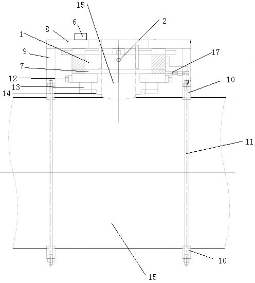
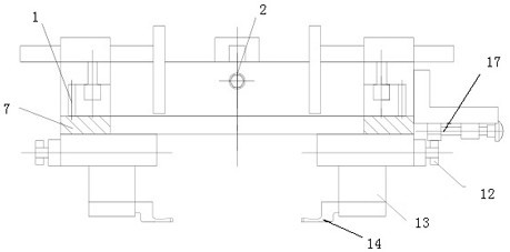
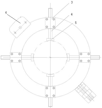
[0028] Such as figure 1 , figure 2 and image 3 As shown, a quick cutting device for oil stealing valve cover includes a fixed part and a rotating part, and a fastening mechanism is installed on the fixed part; There is a through hole, and a locking device telescopic screw 2 passes through the through hole, and a locking device fixing seat 3 is installed on the upper surface of the fixed rotary disk 1 corresponding to the through hole, and there is a locking device fixing seat 3 in the locking fixing seat 3 The locking device guiding rod 4 passes through, and the locking device guiding rod 4 ha...


PUM


Abstract

The invention discloses a quick cutting device for an oil stealing valve cover cap, which comprises a fixed part and a rotating part, and a fastening mechanism is mounted on the fixed part; the fixing component comprises a fixing rotary disc, a through hole is formed in the side face of the fixing rotary disc, a locking device telescopic screw penetrates through the through hole, a locking device fixing base is installed on the upper surface, corresponding to the through hole, of the fixing rotary disc, a locking device guide rod penetrates through the locking fixing base, and the locking device guide rod and the locking device telescopic screw are the same in length. The bottom surface of the locking device guide rod and the bottom surface of the locking device telescopic screw rod are coplanar and are provided with a locking seat; a driving gearbox is arranged above the fixed rotary disc; the rotating component comprises a rotating disk, and a feeding and retracting control device is installed on the side face of the rotating disk. The oil stealing valve cap cutting device is simple in structure and convenient to install, no spark is generated in the whole process, the potential safety hazards such as flash burning and flash explosion of cutting off the cap are thoroughly avoided, and the oil stealing valve cap can be cut off at the root no matter where the oil stealing valve cap is located on an oil conveying pipeline.

Description

technical field [0001] The invention relates to a dismantling device for an oil stealing valve of an oil pipeline in the petroleum industry, in particular to a quick cutting device for a cover cap of an oil stealing valve. Background technique [0002] After the completion of the pipeline, oil thieves were rampant, and the situation of oil thieves was severe. Therefore, oil thieves often used caps for emergency treatment. Leave a lot of oil stealing valve cover caps. With the deepening of pipeline management work, it is required to gradually remove the old oil stealing valve cover cap on the oil pipeline. [0003] During the process of removing the oil stealing valve cover, it was found that most of the old valves and low-pressure valves in the oil stealing cover cap, under the condition of long-term high pressure, there will be a certain residual pressure or oil and gas. [0004] At present, the most commonly used method of cutting the cap is to use an angle grinder to c...

Claims


Application Information

Patent Timeline
IPC IPC(8): B23D17/02B23D79/00B23Q5/28B23Q11/10
CPCB23D79/00B23Q11/10B23D17/02B23Q5/28B23Q11/1038
Inventor 陈重阳朱晓东安晓雷王晓东鞠磊许付晓崔璇李宏英周健宋可兴项玉婷孙滨滨王栋薛燕
Owner PIPECHINA SOUTH CHINA CO
Learn More