Presser foot replacement device for circuit board drilling

A circuit board and presser foot technology, which is applied in the field of presser foot replacement devices for circuit board drilling, can solve problems such as inaccurate installation position, poor drilling quality, affecting drilling quality and hole position accuracy, and reduce manual operations , Improve efficiency, improve drilling quality and hole position accuracy

Active Publication Date: 2022-05-03
四川英创力电子科技股份有限公司
View PDF0 Cites 0 Cited by
  • Summary
  • Abstract
  • Description
  • Claims
  • Application Information

AI Technical Summary

Problems solved by technology

[0002] When drilling printed circuit boards, in order to prevent drilling deviation, drill bit breakage and poor drilling quality, presser feet are added when the main shaft of the drilling rig touches the board surface. Before drilling, the presser feet first press the board surface. Then drill again, but because the diameter of the drill bit is different, it will affect the drilling quality and hole position accuracy. Therefore, in order to ensure the drilling quality and hole position accuracy, it is necessary to replace different diameter drill bits according to different drill bit diameters during drilling. The presser foot is now replaced manually, which will easily cause the installation position of the presser foot to be inaccurate after replacement, thus affecting the drilling quality and hole position accuracy

Method used


Image

  • Presser foot replacement device for circuit board drilling
  • Presser foot replacement device for circuit board drilling
  • Presser foot replacement device for circuit board drilling

Examples


Embodiment approach

[0044] The specific implementation is described as follows:

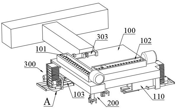
[0045] Such as figure 1 As shown, when the presser foot on the left side of the base 400 needs to be replaced, the linear mechanism is first activated to move the support base 100 to the corresponding position of the base 400, and then the turning mechanism is activated so that the support base 100 is directly above the base 400. Then start the first motor 202 located on the left side, drive the screw mandrel 201 in the first chute 101 to rotate, make the slide block 203 move towards the base 400 from the position of the lifting frame 306, start the first telescopic link 204, and make the connecting plate 205 Move downwards. During the movement, the clamping rod 206 passes through the hole on the presser foot. Since the movable plate 210 is hinged to the lower end of the support plate 207, the movable plate 210 is lifted up by the presser foot to avoid the clamping process. 210 interferes with the presser foot, and...


PUM


Abstract

A presser foot replacement device for circuit board drilling, relating to the technical field of circuit board production and processing equipment, including: a support seat, a clamping mechanism, a transfer mechanism, and a base; Groove and the second chute; the clamping mechanism includes two clamping assemblies, which are arranged along the length direction of the first chute and the second chute, for clamping the presser foot; the transfer mechanism includes the first transfer assembly and the second transfer The components are all installed on the support base and are used to transfer the presser feet clamped by the clamping components. The first transfer component is located on the side of the first chute close to the end of the support rod, and the second transfer component is located on the second chute away from the first One end of the chute; the base is installed on the circuit board drilling equipment, and is located between one end of the first chute and one end of the second chute, and is used to carry the presser foot; it can automatically carry out the presser foot on the drilling equipment Replacement, reduce manual operation, ensure accurate installation position of presser foot, improve drilling quality and hole position accuracy.

Description

technical field [0001] The invention relates to the technical field of circuit board production and processing equipment, in particular to a presser foot replacement device for circuit board drilling. Background technique [0002] When drilling printed circuit boards, in order to prevent drilling deviation, drill bit breakage and poor drilling quality, presser feet are added when the main shaft of the drilling rig touches the board surface. Before drilling, the presser feet first press the board surface. Then drill again, but because the diameter of the drill bit is different, it will affect the drilling quality and hole position accuracy. Therefore, in order to ensure the drilling quality and hole position accuracy, it is necessary to replace different diameter drill bits according to different drill bit diameters during drilling. Presser feet are now replaced manually, which can easily cause inaccurate installation positions after replacement of the presser feet, thus affe...

Claims


Application Information

Patent Timeline
Patent Type & Authority Patents(China)
IPC IPC(8): B26F1/16H05K3/00B26D7/02
CPCB26F1/16H05K3/0047B26D7/025B26F2210/08
Inventor 李清华张仁军林涛牟玉贵杨海军
Owner 四川英创力电子科技股份有限公司
Why Eureka
Try Eureka