Automatic brake control device

A control device and automatic braking technology, applied in the direction of brake transmission, pneumatic brake, brake, etc., can solve the problems of slow inflation speed and poor braking effect, and achieve fast exhaust speed and good emergency braking effect. , the effect of improving working conditions

Inactive Publication Date: 2022-03-25
山东智捷专用车制造有限公司
View PDF4 Cites 0 Cited by
  • Summary
  • Abstract
  • Description
  • Claims
  • Application Information

AI Technical Summary

Problems solved by technology

The above braking method needs to flush the compressed air of the auxiliary air cylinder into the brake cylinder when braking, which has the problems of slow inflation speed and poor braking effect

Method used


Image

  • Automatic brake control device

Examples


Embodiment 1

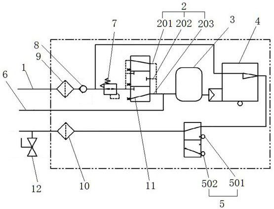
[0024] like figure 1 As shown, an automatic braking control device involved in this embodiment includes a main air duct 1, a main air dust filter 9, a one-way valve 8, a pressure reducing valve 7, a control valve 2, an equalizing air cylinder 3, Action valve 4, emergency exhaust valve 5, train pipe dust filter 10 and train pipe 6; exhaust train pipe ball valve 12 is set on the train pipe 6; the inner diameter of the total air pipe 1 is 21mm; the passage a11 The exhaust diameter is 16mm; the exhaust diameter of the emergency brake is 21mm; the control valve 2 includes a relief position 201, a pressure maintaining position 202 and a braking position 203, and the control valve 2 controls the The position of the control valve 2 ; the emergency exhaust valve 5 includes a normal position 501 and an emergency position 502 .

[0025] When the emergency exhaust valve 5 is placed in the normal position 501, the control device is in a normal working mode, and the normal working mode inc...


PUM


Abstract

The invention relates to the technical field of automatic control, in particular to an automatic brake control device, and solves the problems of low inflation speed and poor brake effect in the prior art. The system structurally comprises a main blast pipe, a control valve, a balancing air cylinder, an operating valve, an emergency exhaust valve and a train pipe which are connected in sequence, a pressure reducing valve is arranged between the main blast pipe and the control valve; the emergency exhaust valve comprises a normal position and an emergency position; when the emergency exhaust valve is arranged at the emergency position, the train pipe exhausts air, and the control device brakes emergently; when the emergency exhaust valve is arranged at a normal position, the control device is in a normal working mode, when the pressure in the train pipe is increased, the train is relieved, when the pressure in the train pipe is reduced, the train brakes normally, and when the pressure in the train pipe is not changed, the pressure of the train is maintained. Emergency braking or normal braking of the train can be achieved in the mode of exhausting the train pipe, the exhausting speed is high, and the better emergency braking effect is achieved.

Description

technical field [0001] The invention relates to the technical field of automatic control, in particular to an automatic braking control device. Background technique [0002] Automatic control devices are generally used for locomotive brakes, which can realize common braking and emergency braking of trains. The brake devices installed on existing rolling stock are usually air brakes, which use compressed air to generate braking force. Brake pipe venting brake, that is, locomotives, railcars or other power vehicles fill compressed air into the brake pipe of the continuous train. When the air pressure in the brake pipe is lower than the air pressure of the auxiliary air cylinder, it is stored in the auxiliary air cylinder. The compressed air will be filled into the brake cylinder, the compressed air will push the piston of the brake cylinder, and the piston will push the brake shoe to hold the wheel set tightly, so as to brake the train. The above-mentioned braking method need...

Claims


Application Information

Patent Timeline
Patent Type & Authority Applications(China)
IPC IPC(8): B61H11/10B60T13/24B60T13/70B60T17/04
CPCB61H11/10B60T13/24B60T13/70B60T17/04
Inventor 岳公华岳亮朱绍华彭东吉董元珂岳浩然曹平先杜连明
Owner 山东智捷专用车制造有限公司
Why Eureka
Try Eureka