Feeding system

A feeding system and feeding technology, applied in auxiliary welding equipment, welding equipment, manufacturing tools, etc., can solve the problems of high cost and low feeding efficiency, so as to avoid machine failure, improve welding efficiency, and increase feeding rate Effect

Pending Publication Date: 2022-03-25
SHANGHAI YONGTAI AUTOMOBILE PARTS CO LTD
View PDF0 Cites 0 Cited by
  • Summary
  • Abstract
  • Description
  • Claims
  • Application Information

AI Technical Summary

Problems solved by technology

In the prior art, manual feeding is usually used, and the feeding efficiency is low and the cost is high

Method used


Image

  • Feeding system
  • Feeding system
  • Feeding system

Examples


Embodiment Construction

[0027] In order to make the technical means, creative features, goals and effects of the present invention easy to understand, the following embodiments will specifically illustrate a material supply system of the present invention in conjunction with the accompanying drawings.

[0028] The feeding system in this embodiment includes a sorting and conveying device 100 and a feeding device 200 .

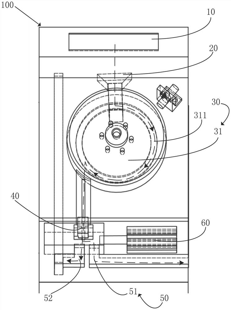
[0029] figure 1 It is a cross-sectional view of the sorting and conveying device of the feeding system in this embodiment.

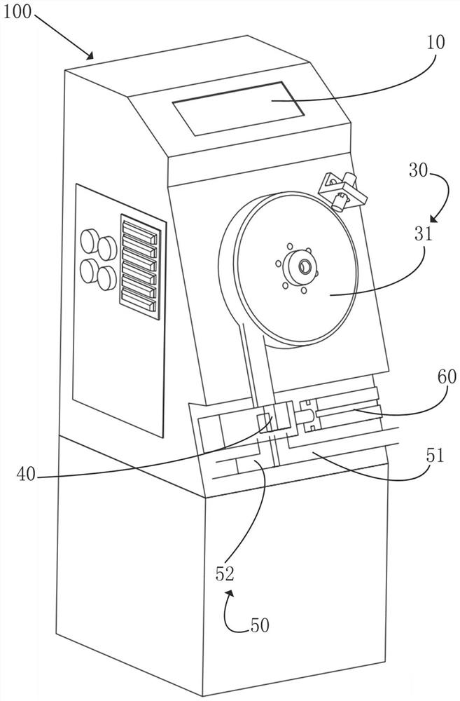
[0030] figure 2 It is an overall schematic diagram of the sorting and conveying device of the feeding system in this embodiment.

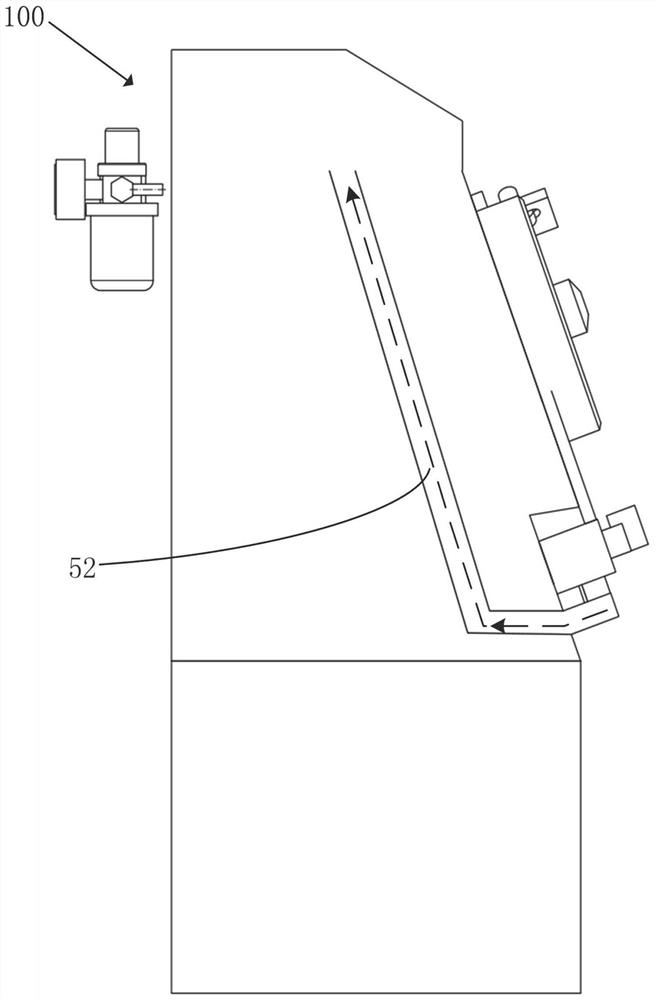
[0031] image 3 It is the left view of the sorting and conveying device of the feeding system in this embodiment;

[0032] Such as Figure 1 ~ Figure 3 As shown, the sorting and conveying device 100 of this embodiment includes a holding part 10, a connecting part 20, a conveying part 30, an induction part 40, a sorting and conv...


PUM


Abstract

The invention discloses a feeding system which is characterized in that the feeding system comprises a sorting and conveying device used for sorting and conveying thin plate nuts so as to provide the thin plate nuts in accordance with a preset orientation; the feeding device is used for conveying the thin plate nuts from the sorting and conveying device to a designated position, and the feeding device comprises a conveying part connected with the first conveying channel and used for conveying the thin plate nuts; the pushing part is connected with the conveying part and used for pushing the thin plate nut to a designated position; and the clamping part is used for clamping the thin plate nut, and the pushing part pushes the thin plate nut into the clamping part. The feeding system has the function of automatically sorting and conveying the thin plate nuts, and the thin plate nuts can be conveyed to the thin plate in the same direction to be welded. And a thin-plate nut feeding function is achieved, the thin-plate nuts can be automatically conveyed in sequence, and the welding efficiency is improved.

Description

technical field [0001] The invention relates to the technical field of auto parts processing, in particular to a feeding system. Background technique [0002] In the current parts processing process, the welding connection of thin plates and thin plate nuts has been widely used. Sheets in the prior art such as Figure 6 as shown, Figure 6 The left side is a schematic diagram of the thin plate, and the right side is a side view after welding the thin plate nut. Figure 7 It is a schematic diagram of a sheet nut in the prior art. Such as Figure 6 and Figure 7 As shown, there are three protrusions on one side of the thin plate nut 80 , that is, three welding points for welding with the thin plate 70 . [0003] Since the welding convex surface of the sheet nut needs to face the sheet nut when the sheet nut is welded to the sheet, it is necessary to select the orientation of the welding projection of the sheet nut before welding. In the prior art, manual sorting is usually...

Claims


Application Information

Patent Timeline
IPC IPC(8): B65G47/256B65G47/82B23K37/00
CPCB65G47/256B65G47/82B23K37/00B65G2203/0225
Inventor 朱海瑞
Owner SHANGHAI YONGTAI AUTOMOBILE PARTS CO LTD
Why Eureka
Try Eureka