
Battery cell diaphragm unwinding process and diaphragm unwinding device thereof

A diaphragm and cell technology, which is applied in the field of cell diaphragm unwinding process and its diaphragm unwinding device, can solve the problems of surface wrinkles and bending of flexible diaphragm belts, uneven surface flatness of diaphragm, affecting the quality of laminations, etc. Achieve the effect of ensuring the consistency of internal tension, improving lamination efficiency and improving surface quality

Pending Publication Date: 2022-03-25
SHENZHEN XING GRAIN AUTOMATION CO LTD
View PDF11 Cites 0 Cited by
  • Summary
  • Abstract
  • Description
  • Claims
  • Application Information

AI Technical Summary

Problems solved by technology

The technical problems that need to be solved in the process of diaphragm discharging and laminated film covering include: 1. The tension adjustment problem during diaphragm discharging. During the process from reel discharging to film covering, when the flexible material strip diaphragm is exported, it is received from the outside. Affected by various factors, the tension in various places will change, and the change in tension will cause the flatness of the diaphragm surface to be different during the subsequent film covering, which will affect the quality of the cell stack. Tension consistency in the process; 2. Diaphragm position offset problem. During the transmission process, the diaphragm will be affected by external factors and changes in the tension of the rear section, and the position will be offset. Because the latter lamination process requires the diaphragm to be completely covered on the pole On the surface of the sheet, the position of the diaphragm will not be able to completely cover the pole piece after the position of the diaphragm is shifted, which will affect the quality of the stack. Therefore, it is necessary to solve the problem of the diaphragm position shift when the diaphragm is discharged; The belt-shaped diaphragm is released by the ground rotation movement, and the film coating process of the latter stage is intermittent film pulling, film covering, and film pressing, and the diaphragm is directly connected to the film from the material roll, which is technically difficult and cannot guarantee the quality of the diaphragm. Maintain tension, that is, when the released diaphragm belt is more than the film-covering demand, the diaphragm is in a relaxed state; when the released diaphragm tape is less than the film-covering demand, the diaphragm is in an over-tensioned state, and the tension of the diaphragm changes frequently. It is very easy to cause the surface of the flexible diaphragm belt to wrinkle, bend, etc. Therefore, it is necessary to solve the problem of diaphragm buffering, by solving the problem of diaphragm buffering, to realize that the diaphragm is always in a state of tension during the process of feeding and covering, and effectively connect the actions of discharging and covering ;4. The problem of automatic alternate coating of belt-shaped diaphragms. The battery stack is to alternately stack the positive and negative electrodes on the stacking platform. At the same time, it is required to alternately insert the strip-shaped diaphragms into the adjacent Between the positive and negative pole pieces, it is necessary to solve the problem of alternate coating of the strip pole piece; 5. The tension detection problem during the strip diaphragm coating process, when the strip diaphragm is pulled out to the lamination platform and covered on the surface of the pole piece , the diaphragm tension directly affects the flatness of the diaphragm surface after film coating, so it is necessary to solve the problem of diaphragm tension detection, by monitoring the diaphragm tension in real time, and adjusting the tension after feedback, so as to ensure the consistency of tension and the quality of film coating

Method used


Image

  • Battery cell diaphragm unwinding process and diaphragm unwinding device thereof
  • Battery cell diaphragm unwinding process and diaphragm unwinding device thereof
  • Battery cell diaphragm unwinding process and diaphragm unwinding device thereof

Examples


Embodiment Construction

[0033] The present invention will be further described below in conjunction with accompanying drawing:

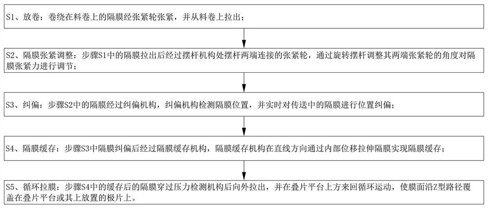
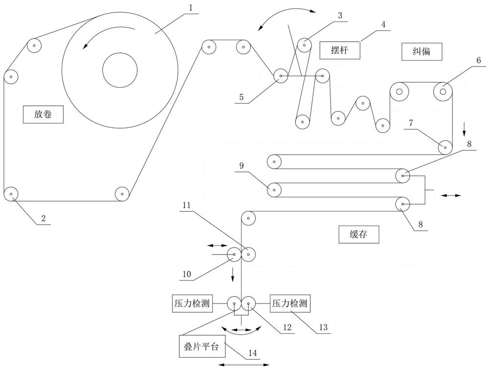
[0034] Such as Figure 1 to Figure 4 As shown, the technical scheme adopted by the present invention is as follows: a cell diaphragm unwinding process, comprising the following process steps:

[0035] S1. Unwinding: the diaphragm wound on the roll is tensioned by the tensioning wheel and pulled out from the roll;

[0036] S2. Diaphragm tension adjustment: After the diaphragm in step S1 is pulled out, it passes through the tensioning wheels connected at both ends of the swing rod at the swing rod mechanism, and adjusts the tension force of the diaphragm by rotating the swing rod to adjust the angle of the rollers at both ends of the swing rod ;

[0037] S3, deviation correction: the diaphragm in step S2 passes through the deviation correction mechanism, and the deviation correction mechanism detects the position of the diaphragm, and corrects the position of the diaphragm ...


PUM


Abstract

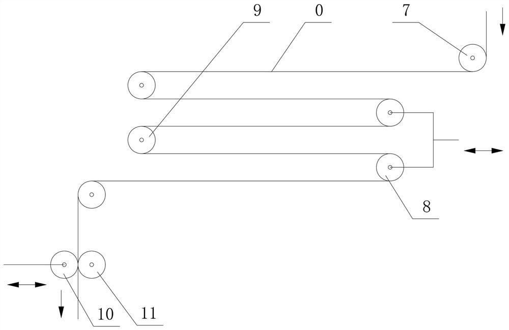
The invention discloses a battery cell diaphragm unwinding process and a diaphragm unwinding device thereof, and the battery cell diaphragm unwinding process comprises the following process steps: S1, unwinding; s2, diaphragm tensioning adjustment; s3, deviation rectification; S4, diaphragm buffering; and S5, circularly drawing the film. The battery cell diaphragm unwinding device comprises a material roll, a swing rod mechanism, a deviation rectifying mechanism, a buffering mechanism, double rollers and a diaphragm drawing roller, and a belt-shaped diaphragm is wound on the material roll; the deviation rectifying mechanism is arranged at the rear section of the oscillating bar mechanism; the caching mechanism is arranged at the rear section of the deviation rectifying mechanism; the double rollers are arranged at the rear section of the caching mechanism; the membrane drawing roller is arranged at the rear section of the double rollers, and the membrane drawing roller drives the membrane to circularly move back and forth above the lamination platform after pressing the membrane, so that the membrane horizontally covers the lamination platform or the pole piece. The film laminating machine has the functions of diaphragm tension adjustment, position deviation correction, automatic buffer connection, tension detection and the like, continuous tensioning of the diaphragm and consistency of internal tensioning force are guaranteed, the surface quality of a laminated film is improved, and the laminating efficiency is effectively improved.

Description

technical field [0001] The invention relates to the field of automation equipment, in particular to a battery diaphragm unwinding process and a diaphragm unwinding device. Background technique [0002] Lithium battery refers to batteries containing lithium in the electrochemical system, including metal lithium, lithium alloys, lithium ions, and lithium polymers. Lithium batteries can be roughly divided into two categories: lithium metal batteries and lithium ion batteries. Lithium battery is a rechargeable battery that mainly relies on lithium ions to move between positive and negative electrodes to work. During charging and discharging, lithium ions intercalate and deintercalate back and forth between the two electrodes: when charging the battery, lithium ions are deintercalated from the positive electrode, inserted into the negative electrode through the electrolyte, and the negative electrode is in a lithium-rich state; the opposite is true during discharge. A battery t...

Claims


Application Information

Patent Timeline
IPC IPC(8): B65H23/188B65H23/032B65H20/34B65H26/04H01M10/0583
CPCB65H23/1888B65H23/032B65H20/34B65H26/04H01M10/0583B65H2701/1133Y02E60/10Y02P70/50
Inventor 周贤文彭强宾兴徐骏
Owner SHENZHEN XING GRAIN AUTOMATION CO LTD
Learn More