Automatic cut-off condition identification method for valve chamber containing compressor gas transmission main line
An automatic cut-off and identification method technology, which is applied in the direction of mechanical equipment, gas/liquid distribution and storage, complex mathematical operations, etc., can solve the problem that there is no improvement in the shut-off identification conditions of the cut-off valve in the gas transmission trunk line of the compressor, so as to reduce the error The effect of judging probability, reducing misjudgment, and reducing false shutdown
- Summary
- Abstract
- Description
- Claims
- Application Information
AI Technical Summary
Problems solved by technology
Method used
Image
Examples
Embodiment 1
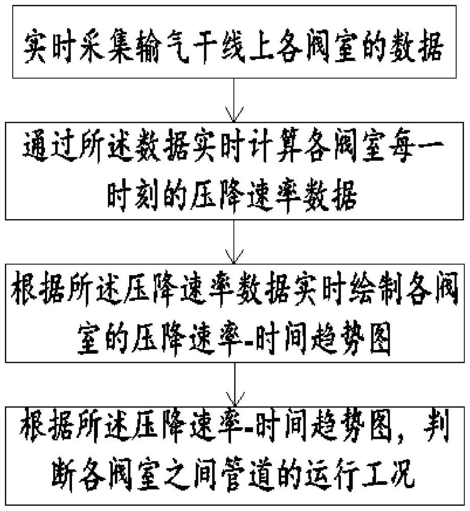
[0035] Such as Figure 1 to Figure 5 As shown, the present invention discloses a method for identifying the automatic cut-off condition of the valve chamber of the gas transmission trunk line containing the compressor, which includes the following steps:
[0036] Step S1: Collect data of each valve chamber on the main gas transmission line in real time; the data includes gas pressure, gas delivery volume and gas composition data in the pipeline at each valve chamber.
[0037] Step S2: Calculate the pressure drop rate data of each valve chamber in real time according to the data; the calculation formula of the pressure drop rate is:
[0038]
[0039] Where: V i is the pressure drop rate, T i is the i-th time node when the data is collected, P i for at time T i The valve chamber pressure collected at the time.
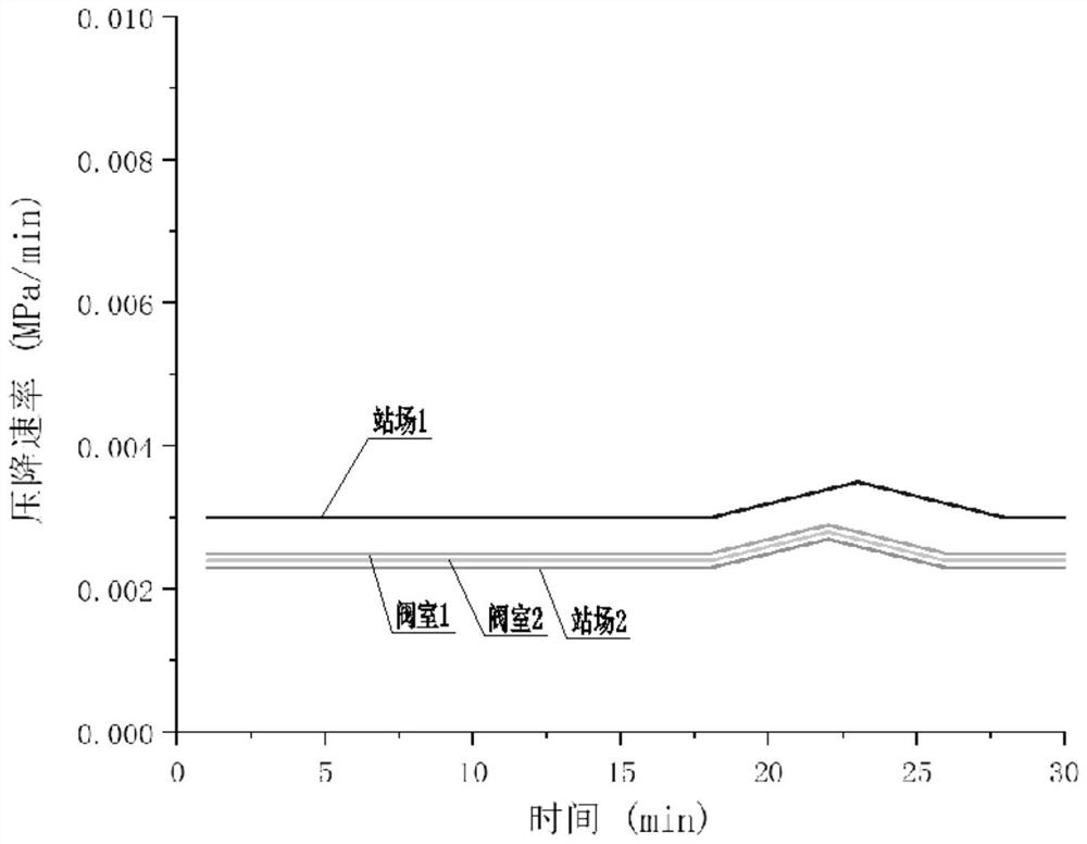
[0040] Step S3: Draw the pressure drop rate-time trend graph of each valve chamber in real time according to the pressure drop rate data;
[0041] Step S4, acco...
Embodiment 2
[0045] This embodiment is based on Embodiment 1, and the data is collected and calculated by an automatic control system. The automatic control system is also connected with a display screen for displaying the pressure drop rate-time trend graph. The automatic control system includes a plurality of execution modules, the plurality of execution modules are respectively arranged in the valve chamber and / or the station, and the execution modules are used to close the pipeline.
[0046] The data is collected and calculated by the automatic control system, which can make the collection process and calculation process faster and more accurate. The display screen can display the pressure drop rate-time trend graph in real time, which is convenient for the on-duty personnel to observe and monitor in real time, and can be timely when the pipeline leaks. Respond to avoid greater losses due to time delays. The execution module can directly act on the pipelines in the valve chamber and / o...
Embodiment 3
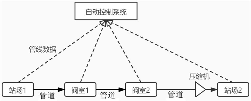
[0049] In this embodiment, on the basis of Embodiment 1 and Embodiment 2, as a specific calculation example, a gas transmission trunk line in a certain area is taken as an example. The gas transmission trunk line includes two gas transmission stations and two shut-off valves There is a compressor in the station 2, and each station and valve room is equipped with a pipeline shut-off valve. The structural diagram of the main gas transmission line can be referred to figure 2 . The diameter of the pipeline is 813×14.2mm, the design pressure is 10MPa, and the transmission medium of the pipeline is the same purified natural gas, which does not contain H 2 S, with a small amount of CO 2 . Now according to the method of the present invention, it is judged whether each shut-off valve of the pipeline needs to be shut off, and the implementation steps are as follows:
[0050] Step 1, collect the real-time pressure, delivery volume, and natural gas composition data of each valve chamb...
PUM
 Abstract
Description
Claims
Application Information
 - R&D
- Intellectual Property
- Life Sciences
- Materials
- Tech Scout
- Unparalleled Data Quality
- Higher Quality Content
- 60% Fewer Hallucinations
Browse by: Latest US Patents, China's latest patents, Technical Efficacy Thesaurus, Application Domain, Technology Topic, Popular Technical Reports.
© 2025 PatSnap. All rights reserved.Legal|Privacy policy|Modern Slavery Act Transparency Statement|Sitemap|About US| Contact US: help@patsnap.com


