Unstable hedging flame burner structure with height controllable speed boundary

A speed boundary and flame combustion technology, applied in the direction of burner, burner, burner cooling, etc., can solve the problem of unable to form a controllable unsteady flame, achieve uniform speed distribution, increase hedging speed, and improve stability Effect

Active Publication Date: 2022-03-25
WUHAN UNIV OF TECH
View PDF6 Cites 1 Cited by
  • Summary
  • Abstract
  • Description
  • Claims
  • Application Information

AI Technical Summary

Problems solved by technology

[0007] The purpose of the present invention is to overcome the problem of being unable to form a controllable unsteady flame in the prior art, and to provide an unsteady opposite flame burner with a highly controllable velocity boundary forming a stable unsteady opposing flame structure

Method used


Image

  • Unstable hedging flame burner structure with height controllable speed boundary
  • Unstable hedging flame burner structure with height controllable speed boundary
  • Unstable hedging flame burner structure with height controllable speed boundary

Examples


Embodiment 1

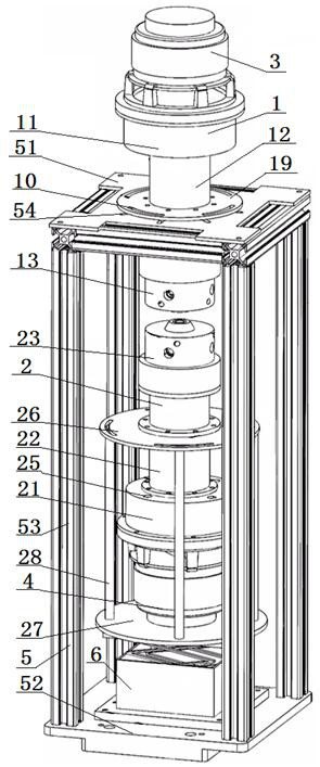
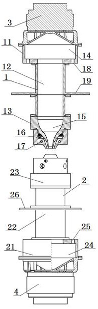
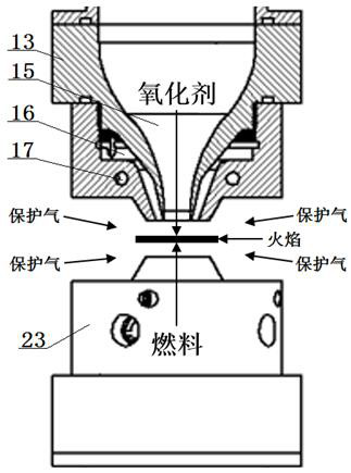
[0050] An unsteady opposed flame burner structure with a highly controllable velocity boundary, the burner includes: an oxidant injector 1 and a gaseous fuel injector 2 arranged oppositely up and down, the oxidizing gas injector 1 and the gaseous fuel The injector 2 is arranged coaxially along the vertical direction, the injection ports of the oxidizing gas injector 1 and the gaseous fuel injector 2 are arranged oppositely up and down, and the top of the oxidizing gas injector 1 is provided with a gas vibration generator 3 at the oxidant end , the oscillation generating end of the gas vibration generator 3 at the oxidant end is set facing the gas injection channel of the oxidizing gas injector 1, the gas vibration generator 4 at the fuel end is arranged at the bottom of the gaseous fuel injector 2, and the gas vibration generator 4 at the fuel end is arranged at the bottom of the gaseous fuel injector 2. The vibration generating end of the vibration generator 4 is set facing th...

Embodiment 2

[0053] Embodiment 2 is basically the same as Embodiment 1, and its difference is:

[0054]The burner also includes: a burner bracket 5, the burner bracket 5 is a cuboid metal frame structure, and the burner bracket 5 is fixedly connected to the middle part of the oxidant injector 1 through an upper fixing plate 51 provided on the top thereof, so that The bottom of the burner bracket 5 is provided with a lower fixing plate 52, the four corners of the lower fixing plate 52 are fixedly connected with the four corners of the upper fixing plate 51 through four columns 53, and the middle part of the top surface of the lower fixing plate 52 is fixed with a height Regulator 6, the lifting adjustment end at the top of the height regulator 6 is fixedly connected to the bottom of the gaseous fuel injector 2; the outer middle section of the oxidant end steady flow pipeline 12 is provided with an oxidant end fixing plate 19, and the oxidant end is fixed The disc 19 is connected with the up...

Embodiment 3

[0056] Embodiment 3 is basically the same as Embodiment 2, and its difference is:

[0057] The steady flow pipeline 12 at the oxidant end is set through the through hole in the middle of the upper fixing plate 51, and the upper fixing plate 51 is provided with a plurality of oblong holes 54 arranged radially along the middle through hole. A plurality of arc-shaped holes 10 are evenly distributed on the circumference concentric with the oxidizer end steady flow pipeline 12, and the oxidant end fixing plate 19 is fixed on the upper fixing plate 51 by bolts, and the bolts pass through the arc holes in turn After 10 oblong holes 54 are connected with nuts.


PUM


Abstract

According to the unsteady-state hedging flame burner structure with the height controllable speed boundary, a burner comprises an oxidizing agent injector and a gaseous fuel injector which are oppositely arranged up and down, and the oxidizing agent injector and the gaseous fuel injector are coaxially arranged in the vertical direction; an injection opening of the oxidizing gas injector and an injection opening of the gaseous fuel injector are oppositely arranged up and down, an oxidizing agent end gas vibration generator is arranged at the top of the oxidizing gas injector, and the oscillation generating end of the oxidizing agent end gas vibration generator directly faces a gas injection channel of the oxidizing gas injector; a fuel end gas vibration generator is arranged at the bottom of the gaseous fuel injector, and an oscillation generating end of the fuel end gas vibration generator is arranged right opposite to a gas injection channel of the gaseous fuel injector. According to the design, unsteady flame with controllable outlet speed boundary height can be formed, and the influence of different waveform conditions on opposed firing soot can be accurately observed.

Description

technical field [0001] The invention relates to an unsteady counter flame burner structure with a highly controllable velocity boundary, which is particularly suitable for simulating a one-dimensional structure unsteady flame in a non-premixed combustion state. Background technique [0002] Soot is carbonaceous particles produced by the incomplete combustion of hydrocarbon fuels. It is mainly composed of carbon elements and may also contain a small amount of hydrogen and oxygen. It mainly comes from mobile sources such as vehicles, ships, construction machinery, and stationary sources such as thermal power plants. The existence of soot will cause many adverse effects including mechanical problems such as combustion system efficiency reduction, environmental problems such as global warming and smog, and human health problems such as lung, respiratory system, and blood system diseases. It is important to conduct in-depth research to reduce soot emissions. [0003] However, th...

Claims


Application Information

Patent Timeline
Patent Type & Authority Applications(China)
IPC IPC(8): F23D14/48F23D14/46F23D14/68F23D14/78F23D14/70F23C5/28
CPCF23D14/48F23D14/46F23D14/68F23D14/78F23D14/70F23C5/28F23D2214/00Y02E20/34
Inventor 张际洲王宇李国柱周梦祥颜伏伍
Owner WUHAN UNIV OF TECH
Why Eureka
Try Eureka