
Composite absorber structure of total-absorption high-energy laser energy meter

A high-energy laser and energy meter technology, applied in the field of high-energy laser optical parameter measurement, can solve problems such as incorrect measurement results, energy loss, and increase the diameter of the integrating sphere, so as to improve the ability to resist laser damage and measurement accuracy, and improve the resistance to laser damage. The effect of laser damage capability, ease of processing and installation

Pending Publication Date: 2022-03-25
HEFEI INSTITUTES OF PHYSICAL SCIENCE - CHINESE ACAD OF SCI
View PDF4 Cites 0 Cited by
  • Summary
  • Abstract
  • Description
  • Claims
  • Application Information

AI Technical Summary

Problems solved by technology

However, the simple conical cavity is easy to cause breakdown due to energy accumulation at the top of the cone. If the incident direction is deviated, it is easy to cause the beam to reflect out of the cone, which will cause energy loss and cause incorrect measurement results.
In a single integrating sphere structure, the beam energy may escape from the opening of the sphere. In order to minimize the escaped energy, it is necessary to increase the diameter of the integrating sphere, which makes the volume of the laser energy meter relatively large.

Method used


Image

  • Composite absorber structure of total-absorption high-energy laser energy meter
  • Composite absorber structure of total-absorption high-energy laser energy meter
  • Composite absorber structure of total-absorption high-energy laser energy meter

Examples


Embodiment 1

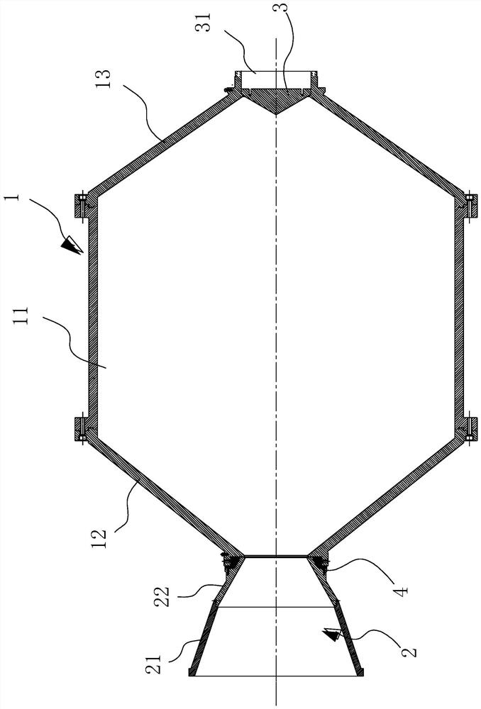
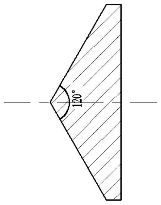
[0031] see figure 1 , a composite absorber structure of a total absorption high-energy laser energy meter, including a main absorber 1, a receiving cone 2, and a reflector 3. The main absorber 1 is a combined cavity, the receiving cone 2 is movably connected with the opening of the main absorber 3, the receiving cone 2 is composed of two conical structures with different cone angles that are movably connected, and the reflector 3 is located in the main absorber 1, the bottom opposite to the opening of the main absorber 1, the main absorber 1 and the receiving cone 2 are connected by a connecting transition piece 4 with low thermal conductivity. When the high-energy laser beam is incident in the direction parallel to the axis of the receiving cone 2 and the main absorber 1, it enters the main absorber 1 after being reflected by the inner surface of the receiving cone 2, and is absorbed by the main absorber 1 after multiple reflections on the inner surface of the main absorber 1...

Embodiment 2

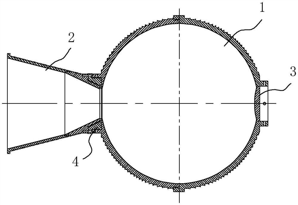
[0044] A composite absorber structure of a total absorption high-energy laser energy meter, comprising a main absorber 1, a receiving cone 2, and a reflector 3. In this example, see image 3 , the main absorber 1 is a spherical cavity connected by two hemispherical cavities.

[0045] The outer surfaces of the main absorber 1 and the receiving cone 2 are provided with spiral grooves or several linear grooves (shown in the figure), and temperature sensors are evenly distributed in the grooves for measuring the main absorber 1 and the receiving cone 2 before and after the laser incident. The measured value of the temperature increment can accurately characterize the overall average temperature rise of the absorber.

[0046] The reflector is a spherical mirror. The rest of the content is the same as that of Embodiment 1, and will not be repeated here.

[0047] The composite absorber structure of the present invention combines the advantages of the conical cavity and the integra...


PUM


Abstract

The invention discloses a composite absorber structure of a total-absorption high-energy laser energy meter. The composite absorber structure comprises a main absorber, a receiving cone and a reflector, the main absorber is a combined cavity, the receiving cone is movably connected with an opening of the main absorber, the receiving cone is composed of two sections of conical structures which are movably connected and have different cone angles, the reflecting mirror is located in the main absorber and at the bottom opposite to the opening of the main absorber, and the main absorber and the receiving cone are connected through a connecting transition piece with low thermal conductivity. A high-energy laser beam is incident in the direction parallel to the axes of the receiving cone and the main absorber, is reflected by the inner surface of the receiving cone, enters the main absorber, and is absorbed after being reflected on the inner surface of the main absorber for multiple times. According to the invention, the overall size of the laser energy meter is effectively controlled, the laser damage resistance of the energy meter is improved, the loss of energy escaping from an opening is reduced, and the measurement accuracy of the high-energy laser energy meter is improved.

Description

technical field [0001] The invention relates to the field of high-energy laser optical parameter measurement, in particular to a composite absorber structure of a total absorption high-energy laser energy meter. Background technique [0002] Accurate measurement of the output energy of high-energy lasers is an important index for evaluating the quality of lasers and the level of laser development. For the quantitative measurement of high-energy laser energy, if indirect methods such as attenuation and sampling are used, the sampling ratio of the attenuation and sampling components is easy to change under the action of the laser. A small change in the sampling ratio will lead to large errors in energy measurement. Therefore direct measurements are required. The traditional photoelectric method and pyroelectric method are not applicable, and the calorimetric method is usually used. The calorimetry method can realize the complete absorption measurement of the laser energy dir...

Claims


Application Information

Patent Timeline
Patent Type & Authority Applications(China)
IPC IPC(8): G01M11/02G01J1/02
CPCG01M11/02G01J1/02
Inventor 李南乔春红杨高潮张京会胡明冯晓星沈威
Owner HEFEI INSTITUTES OF PHYSICAL SCIENCE - CHINESE ACAD OF SCI
Learn More